Fig. 1. Earth cutout revealing a deep ground close to a standard ground rod at the base of the pole.
Deep Grounding Improves the Ground System
Electrical problems can be solved by reaching down into the earth
|
Article prepared at the request of and with the collaboration of
Mr. Earl Hazan, Contributing Feature Editor, for publication by Taransmission & Distribution World. Article published in the September 1998 edition of Transmission & Distribution World. |
Deep grounding is the practice of driving ground rods, often to the point of refusal, to obtain lower grounding resistance at least cost. The deep rod is assembled from shorter ground rod sections that are coupled together, end to end, as the assembly is driven into the earth. It is one of many techniques used in power and communications engineering to obtain more effective grounding systems to solve or ameliorate electrical problems involving better lightning protection, better relay performance and improved safety. Grounding practices based on NESC rules, that require ground rods at least 8 ft long, have worked well. However, these are minimum requirements that do not guarantee satisfactory performance in every situation. On occasion there is a need to improve grounding because of safety or interference problems. Alternative approaches to grounding improvements include counterpoise, buried grids and chemical grounds. One of the most popular, cost-effective solutions along power distribution lines has been to install more ground rods, either on the surface or in the form of a deep ground. Each ground rod that is added can be visualized as an added parallel resistance that connects the ground system to earth (Fig. 1).
Fig. 1. Earth cutout revealing a deep ground close
to a standard ground rod at the base of the pole.
There are many advantages to going deeper into the earth since the rod penetrates further away from the surface of the earth, where temperature and moisture conditions vary considerably due to time and season. In addition, earth resistivity is lower at deeper penetrations due to the influence of the water table. For example, resistivity drops from 20,000 ohm-meters at the earth's surface, to about 850 ohm-meters at a depth of 40 ft (Fig. 2). The drawback of the deep grounding approach is that it is not always possible to determine how far down the assembly can be driven.

Fig. 2. Earth resistivity as a function
of depth in a deep grounding case.
A Specific Problem
An electromagnetic coupling, between the Navy's ELF radio transmitter facility and the neighboring power distribution circuits in Upper Michigan, produced a signal on distribution line neutrals that caused small currents to circulate between the neutral conductor and earth through the many pole grounds on the system. The ELF signal, nearly indistinguishable from the power signal, produces a potential difference between the neutral wire and earth. This voltage is well behaved, being high for power plants close to the transmitter and decaying rapidly as a function of distance from the transmitter.
The interference in the affected area is much like the spreading ripple on a water surface where the ripple becomes ever smaller as it travels outward from the disturbance center, covering ever increasing areas. There is a large fringe area surrounding the ELF transmitter where a number of facilities and customers are involved and where the interference is at the margin of concern. Since the grounding quality along the distribution line affects the level of induced voltage, the earth resistivity is an important parameter. In the affected areas, earth resistivity averaged 5,000 ohm-meters, indicating that there was room for grounding improvement to lower the level of the induced voltage in the marginal areas.
A blanket measure, designed to minimize overall induction effects, had already been instituted in preparation for the initiation of operations at the ELF transmitter. This measure, which had previously been used at a similar facility in Wisconsin, consisted of ensuring that there was an 8-ft ground rod installed at every pole in the distribution circuit. About 8000 rods were installed near the Michigan transmitter site. While reducing the interference voltage and shrinking the affected area, the installed rods were not sufficient to eliminate all unsafe voltages, especially in areas closer to the transmitter.
The Deep Grounding Solution
Under pressure to reduce operating costs, the two power companies with facilities in the interference area were asked to use the deep grounding protocol along a number of short taps selected by the interference mitigation engineers. The protocol devised addressed the uncertainties of deep grounding by specifying that the deep ground rod could be installed at the base of the pole, using the existing rod at the pole base as the lead section. Alternatively, the deep ground could be installed 16 ft from the pole and connected to the existing ground rod with a buried ground wire. Within this context of deep grounding, a maximum of 8 rods was specified to construct each deep ground for a maximum depth 64 ft. A second attempt could be made to install a ground rod if the first attempt resulted in a rod of less that 8 ft deep. The distance away from a pole to install the deep ground rod was set at 16 ft, based on the rationale that the mutual coupling is minimized by keeping the separation between rods equal to the length of the longest rod and the expectation that the average deep ground rod depth would be 16 ft, or two standard rod lengths.
The Upper Peninsula Power Co. (UPPCO) reworked the grounding at 148 poles on 15 short taps, while Wisconsin Electric Power Co. (WEPCo) did the same at 83 poles on 7 taps. The extent of the installation work reflected the different levels of interference experienced in each company's plant near the transmitter. UPPCO installed most of the deep grounds at the base of the pole working with a small crew though the winter of 1996-97. The presence of snow and ground frost were persuasive arguments to make the installations at the base of the poles. WEPCo installed all deep grounds 16 ft from the pole under the power line, working with a large crew in the summer of 1997. Although there was a difference in the approach and the way the jobs were done, results were very similar.
Altogether, 231 line poles were treated and 791 standard 8-ft rods were installed to an average depth of 30 ft. The deepest rod was 64 ft, which was the maximum allowed under the construction protocol, and occurred 10 times. There were cases where the depth was under 3 ft because of the presence of rock near the surface.
The Installation
The ground rod impedance at the pole was measured with the AMC 3730 meter before and after the grounding installations were made. In addition, the neutral voltage was measured to earth before and after to determine the effect of the improved grounding on the neutral voltage. The average pole grounding resistance was reduced from 258 ohms to 78 ohms, a 3.3-fold improvement in pole ground conductance, which was accompanied by an average interference voltage reduction of 24%, in line with predicted results. The before-improvement resistance distribution curve appeared to drop rapidly to zero at about 1200 ohms, which can be explained by the fact that the meter used for the measurements had a maximum range of 1200 ohms, resulting in many measurements pegging at the 1200-ohm value. It can be assumed, therefore, that there were resistances that were higher than 1200 ohms. Observations after the grounding improvements had been made (Fig. 3) showed that there were few resistances recorded at 1200 ohms.

Fig. 3. Statistical distribution of pole ground resistance
before and after deep grounding.
Since material for this job was minimal and inexpensive, the principal cost was for labor. Common construction equipment was used to clear the site and for burying the connecting wire when the installation was away from the pole. The main tool is a mechanical hammer to drive the rods (Figs 4 and 5).
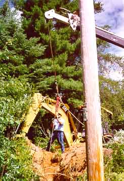
Fig. 4. Hammer on top of driven rod and
suspended from a crane.

Fig. 5. Hammer on top of driven rod being handled by
a worker standing on a raised plow.
Considering that the area was mostly rocky, it was surprising that the deep grounds were, on average, 30 ft deep, with as many as ten reaching the maximum allowed depth of 64 ft. The fact that the average was 30 ft, suggests that a more optimal distance for locating the deep rod away from the pole would have been about 30 ft, instead of the 16 ft that had been specified.
The installation at each pole took about 5 manhours, with a considerable part of the time being expended by deployment, site preparation and job closing. The process of driving a rod to the point of refusal, or to the maximum allowable depth achieved by the 8-rod limit, is a fast and straightforward operation. Once set up, the depth of the ground depends more on luck t han on labor expended. This fact became obvious to the installers when a rock ledge or other obstruction existed that preclude deep grounding in one area. However, at other locations the rod penetrated easily. In addition to encountering hard objects that bring the driving operation to an abrupt halt, there is the soil type that can cause rod "grabbing" due to increased frictional resistance that makes continued hammering ineffective. Although increasing the hammer power may provide additional depth of penetration, there is a limit on the amount of power that can be utilized since buckling of the rod and safety problems may develop. Larger diameter rods and pipes, available for special efforts, were not considered for this work since the job was based on utilizing the standard rod and installation means to keep costs low. Any open protocol that allowed driving to refusal in all cases, without a cap such as the 8 maximum rods in this job, would yield better results with an insignificant amount of additional labor.
Conclusion
Deep grounding can be an effective and inexpensive means of improving grounding effectiveness through the better utilization of rods that reach the deeper layers of the earth that are likely to exhibit higher levels of conductance. The drawback is the presence of surface rock, which makes grounding difficult. Depending on the nature of the soil, grounds as deep as 100 ft have been installed with relatively little effort in similar jobs.
Acknowledgments
The case study described in this article was performed under the technical direction of IIT Research Institute in support of the Navy's ELF Environmental Compatibility Assurance Program. Appreciation is expressed to the Navy, UPPCO, and WEPCo for their support and cooperation. Individuals that have contributed to this effort include J. A. Colby and L. G. Smith of IITRI, J. Miotti and S. Lillie of UPPCO, and T. Seidl and R. Allen of WEPCo.
Biography
Mr. Domenico Lanera joined IITRI in 1972 and has been the chief mitigation engineer for the ELF system in Michigan. He has worked on a variety of R&D projects providing assessment studies, problem investigation and resolution, system engineering design, support engineering services, and engineering management. He is experienced in electrical safety, electromagnetic effects, power systems, computer-based solutions, business processes, and information architectures. He received a BSEE from Illinois Institute of Technology in 1972, and an MBA from University of Illinois at Chicago in 1983.