| Castel del Monte → Elevation Design → Room and Vault Heights – Measurement Analysis |
|
Note: Figures referenced in text are located in a separate file. Follow link to see figures as slides in a separate browser tab: |

|
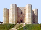
Castel del Monte |
| Castel del Monte → Elevation Design → Room and Vault Heights – Measurement Analysis |
|
Note: Figures referenced in text are located in a separate file. Follow link to see figures as slides in a separate browser tab: |
|
1. Introduction |
|
The plant design is an extraordinary geometric play of octagons. However, there is more to Castel del Monte
than the organic and fractal recurrence of octagons in the plant layout, Fig. 1.
[Figures presented in a separate file, “cdm-152-130=elev-figs-en”.] The castle has two floors with majestic walls that rise in a constellation of plain stone faces, Fig. 2. A new consideration then is the design of the elevated structures and whether this design is related to the ground plant design algorithm. The vault structure and erection process is described in the “Cross Vault Technology” section. There are however questions such as the height of the vaults, the height of the walls, the height of the rooms, and the different room sizes that are separate from the vault construction methodology. These matters are investigated to explore and complete the structural analysis of the castle. Furthermore, an investigation in the room elevations can serve to verify the vault drop from keystone to transverse ribs, which was first theorized from the fishbone pattern in the vault grout lines. It is an analysis that involves both floors and new on-site measurements that were needed specifically for this investigation. |
|
|
|
2. The Elevation Design vs the Plant Design |
|
The plant design of the ground floor is repeated on the upper floor; the bearing walls lineup between the two floors and rise straight up from foundation to roof. The upper floor has eight grand trapezoidal rooms positioned in correspondence of similar trapezoidal rooms on the ground floor, Fig. 3. The trapezoidal rooms with their square cross vaults are most likely lined up vertically with the rooms and their cross vaults on the ground floor as shown in Fig. 3. Measures of the walls on the façade and courtyard sides of the upper floor would provide confirmation.
The vertical lineup of the rooms serves to coordinate supporting walls structures, including the room dividing walls. The vertical lineup is also very important for a resolution to the cross vaults lateral trusts on the upper floor that is consistent with the design established for the ground floor. The towers thus continue to provide the pier function at the upper level; the courtyard wall resolves the inside lateral trusts on the upper floor as well. There is no need for a new structural design for the cross vaults on the upper floor, because the two floors have an identical design. The outdoor sides of the façade and courtyard walls rise uniformly from ground to roof, forming an octagonal toroid of a uniform cross section , Fig. 4. [There are of course some singularities, such as the portal, windows and other details such as the torus on the façade wall that marks the separation between the two floors.] This reinforces the concept of two identical floors that share not just the same footprint but the same exact outside dimensions. The structural similarity in the trapezoidal rooms between the two floors extends to important elements, although there are notable differences in details, style, material and dimensions. The trapezoidal rooms on both floors portray similar structural details:
There is no information on the open spaces inside the towers on the upper floor and whether the tower walls on the upper floor have the same width as on the ground floor. Three of the towers have stairwells; the uniformity of the walls as the stairwells lead to the upper floor suggests that there is no systemic reduction of the tower walls on the upper floor. Maintaining the same tower wall on the upper floor preserves the large masonry mole given to towers in the structural design of the ground plan, to serve as abutments to the cross vault lateral trusts. Measurements are vital to develop theories and ultimately identify the design by the medieval architect. The studies by W. Scirmer and H. Götze of Castel del Monte in the 1990s are the source of most measurement data in this study. Yet, their publications provide few elevation measurements of the room heights. [Wulf Schirmer, Castel del monre, Forschungsergebnisse der Jahre 1990 bis 1996 |
|
|
|
3. Plausibility of the Plant Design Algorithm Extending to the Elevation Designn |
|
It is plausible that the geometric approach that dominates the plant design extends to the elevated structures, mainly the height of the vaults and the height of the rooms on both floors, Fig. 12. The study of the elevated structures of Castel del Monte is challenging because of limited measurement data available from the published literature. Most publications focus on the plant design, because of its unique snowflake-like form that is the hallmark feature of the castle, Fig. 1. Studies of the elevated structures that include measurements are few and tend to focus on the ground floor. The review of elevated structures on the upper floor is typically limited to photos and style discussions. Towers receive special consideration, focused on the spiral stairwells, sanitary services, and the diversity of the vaults.
It is plausible that the structural design that started with the ground plan extends to the elevated structures and serves to establish key measures and proportions, such as the height of walls, the height of vaults, and the height of the rooms. Indeed, the controlling elements in the construction of the vaults are the diagonal and transverse ribs located respectively along the diagonals and sides of the cross vault base square. The span of these ribs is established in the ground plan design, by the dimension given to the cross vault base square, Fig. 13. In contrast, the shape of the vaults is a derivative construction operation that does not require much planning by the designer, as outlined in the “Cross Vault Technology” section . [Masons assembled the vaults using the diagonal and transverse ribs as guides; the size and shapes of these ribs is part of the architectural design.]There are many phases in the design plans of Castel del Monte. The structural design of the elevated structures is a simpler phase that depends much on the ground plan. It is a design repeated in all sections of the castle, preserving the eight-wing rotational symmetry established in the plant design. There is, however, much more to the design of the elevated structures that is separate from the structural considerations. This is the design that involves functions of the various spaces, support facilities, style, finishing stones, etc. Nevertheless, the architectural design of the elevated structures provides essential insights in the structural organization of the castle, and completes the skeletal design. |
|
|
|
4. Leads for a Theorized Design |
|
Key interests in the design of the elevated structures are the heights of the rooms, the height of the walls, the heights of the vaults, the shape of the vault along the crown lines and the dimensions on the upper floor where the rooms are brighter and larger, Fig. 12. The design algorithm that drove the planimetric design of the ground floor is a first consideration in exploring the design of the elevated structures; there are many leads that support this search.
The diagonal of the square at the base of the cross vault is also the diagonal of the two crossing ribs, referred to as the diagonal ribs. [The other four ribs that form the perimeter of the square cross vault are referred to as the transverse ribs and have the iconic gothic form.]These ribs have a semicircle form, subtending the diagonal of the cross vault base square, Fig. 13. This cross vault diagonal thus provides a link between the square at the base, which is part of the plant design, and the height of the vault, which is the radius of the semicircle at the extrados of the diagonal ribs. This tie could have been used to extend the geometric algorithm of the plant design to the elevated structures. Another probable tie is the size of the rooms on the upper floor. The rooms are wider on the upper floor as pointed out by many scholars and readily noticeable. The larger room implies a larger cross vault and a wider room. The room widening is achieved by carving the additional space out of the walls, most significantly on the façade and courtyard sides respectively, Fig. 14. The location for the indoor side of the façade wall was set in the “Concept Plant Design” at the octagon formed by the innermost corners of the eight tower basement octagons. The outdoor side of the façade wall was set in the concept design at the line segments between adjacent towers joining the next-to-innermost corners of the tower octagon, Fig. 15. The choice of the innermost corner of the tower basement octagon for the indoor face of the façade wall seemed an odd choice at first, because logically the innermost corner of the tower octagon would have been a preferable, geometrically more elegant choice. It was noted however that the indoor side of the façade wall on the upper floor was set back compared to the ground floor. A conjecture followed that the setback might be by the measure of the tower footing; this was also a presumption by Götze (pg. 180). This was corroborated by the fact that the wall set back on the upper floor seemed to be marked by a seating bench running around the room. The width of the seat was visually close to the measure of the tower footing. The lack of detailed measures in the published literature for the rooms on the upper floor gave wind to these speculations. A wall setback of the measure of the tower footing on the upper floor would set the indoor side of the façade wall at the octagon formed by the innermost corners of the eight tower octagons. The tower footing thus provides another potential link between the ground plan and the measures of the room on the upper floor. |
|
|
|
5. Theoretical Design – Ground Floor |
|
The diagonal ribs have a semicircular shape and span the diagonal of the cross vault base square. The ribs have a radius that is dependent on the dimension of the cross vault base square and is exactly half the dimension of the base square diagonal. This is verified by Schirmer, Abb. 27, pg. 39. The height of the vault from the vault spring line to its highest point, in correspondence of the keystone, is therefore half the measure of the diagonal of the cross vault base square.
The height of the room is the sum of the height of the vault and the height of the vault spring line above the floor. A geometric solution for the height of the vault spring line comes from the standing circle that completes the semicircle of the diagonal ribs. The geometric model for the elevations is then a “Standing Circle” with the diameter of the cross vault base square in a vertical plane oriented along the cross vault base square diagonal, Fig. 17. The bottom of the standing circle determines the floor, the top semicircle portion determines the profile of the diagonal rib, and the radius of the circle determines the height of the vault. The height of the vault spring line above the floor is also the radius of the standing circle, which is the radius of the semicircle formed by the diagonal ribs, or half the diagonal of the cross vault base square. The erection of the vault is part of the established construction outlined in the “Cross Vault Technology” section. There is no design; the matter was in the hands of the stonemasons that followed the established medieval methodology for constructing cross vaults, requiring no specific direction or other instruction from the architect. The other vault ribs, which ultimately give the Gothic form to the four webs that make up the vault, are the transverse ribs, erected along the four sides of the cross vault base square, Fig. 18. These ribs have a pointed form, which is defined geometrically as the intersection of two round arches, Fig. 19. The radius for these arches is the radius of the diagonal ribs, Figs. 18 and 19. [This too is part of the ribbed cross vault construction methodology whose essence was simplification in stonework needs. Using the same radius for all arches standardized the shape for the ribs voussoirs and simplified the job for stone cutters.]These arches are drawn starting at the corners of the cross vault base square with the radial center lying on the vault spring line, Fig. 19. This is supported by Schirmer, Abb. 27, pg. 39. Accordingly, the height of the transverse ribs at their highest point along the extrados can be determined geometrically, Fig. 19: ht = √(r²- x²), x = r - w/2, w = (2 · r) / √2 where: ht = height of the vault at the transverse ribs w = room width from façade to courtyard side r = radius of the diagonal rib semicircle, or the radius of the theorized standing circle The height of the transverse ribs is accordingly tied to the height of the diagonal ribs and will therefore be different between the ground and upper floors, Fig. 20. Based on this geometry, the height of the transverse ribs must also be shorter that the height of the diagonal ribs, Fig. 19 and 20. The web crown lines, one at each of the four webs, slope down by the same amount starting at the vault center, in correspondence of the keystone, and terminating at the top of the transverse ribs. The slight drop of the vault is noticeable in the diagrams of a vertical cross-cut view of the rooms by Schirmer, Abb. 8 and 9 on pg. 10. The transverse ribs give shape to the cusped, barrel-like sections of the four webs that form the cross vault. However, the web shells are not perfect cylindrical surfaces. [They are assembled with lines of voussoirs on support planks that span from the diagonal ribs to the transverse ribs; refer to the “Cross Vault Technology” section.]They are formed by two roundish surfaces slightly distorted and symmetrically opposite, joined at the web crown line. The special shape of the webs was deduced from the fishbone pattern formed by the web grout lines in the “Cross Vault Technology” section. The warping of the web surfaces from perfect cylindrical shells is not noticeable visually, but does cause a drop of the web crown line from keystone to transverse ribs. There are no published data on the height of the vault at various room locations to address the measure of the drop in the web crown line. Schirmer provides measures of the room height only on the ground floor and only in correspondence of the dividing walls. The theory then is that the height for the room and the vault are a function of the cross vault base square diagonal and, therefore, a function of the room width measured between the façade and the courtyard walls. The latter is an established measure on the ground floor; both Schirmer and Gotze provide detailed measures of this width for each of the eight rooms on the ground floor. The average room width on the ground floor measured from the finished surfaces is 6.400 m with a variation of ±0.015 m among the eight rooms, based on Schirmer’s data. The square vault diagonal is then calculated to be 9.051 m ±0.021 m, that is 29.970 ft ±0.070 ft (CdM-ft). [ (Castel del Monte foot, “CdM-ft”).]The medieval planners likely made the square vault diagonal an even 30.00 ft and the radius of the round arches at the extrados an exact 15 ft; this is a key measure for the stonecutters manufacturing the rib stonework. It is therefore theorized that the height of the room on the ground floor is 30.000 ft, 9.06 m, at the keystone and 29.342 ft, 8.861 m, at the transverse ribs. The four web crown lines drop by 0.658 ft, 0.199 m, going from the keystone toward the transverse ribs; it is a drop in height of 2.2%, imperceptible looking at the vault from the floor. There are no published data of these measures for verification. The theorized height of the vault is 15 ft, 4.53 m; Schirmer reports a measure of 4.52 m in Abb. 27 on pg. 39, which augurs for a successful verification of the theorized heights. The theorized vault spring line is the radius of the diagonal rib, or the height of the vault, which is 15 ft, 4.53 m. The height of the column on the ground floor given by Schirmer, which sets the spring line for the vault, is 4.345 m in Abb. 20 on pg. 27, shorter by 0.185 m than the theorized height. It is a perplexing divergence addressed in a following section with an in depth discussion of the actual measurements. All rooms on the ground floor have the same width and therefore would have the same height at the keystone and at the transverse ribs, and have the same drop of the room height at the transverse ribs. |
|
|
|
6. Theoretical Design – Upper Floor |
|
The upper floor is a replica of the ground floor. It has identical trapezoidal rooms with ribbed cross vaults. The rooms are lined up with the corresponding rooms on the ground floor, sharing the same walls. The rooms on the upper floor are a bit larger and taller than the corresponding rooms on the ground floor.
Why the rooms are larger on the upper floor is a tantalizing question. There are differences from the ground floor in style and material to suggest a separate design approach. Yet it could have been a simple quest for larger rooms. Structurally there is no need to enlarge the rooms, but the medieval designers likely saw differently. A theorized explanation comes from the mind-set of the medieval builders concerning static loads and lateral thrusts associated with massive masonry vaults. With limited knowledge and an intuitive feel for the working of loads and lateral thrusts, it is likely that the medieval designer at Castel del Monte saw a need to provide a footing for some load-bearing structures, much like the base of a column. The towers were given a footing at Castel del Monte in the form of an octagonal basement that is larger than the tower octagon. The footing could have been intended as a decorative feature; however, it is not a feature at the façade wall, Fig. 21. If it was intended solely as a decorative feature, the footing at the towers would likely have been extended to the façade walls, just like the torus. Indeed, marking the separation between the two floors is a torus, which runs continuously around the castle, covering both the towers and the façade wall, Fig. 2. It is posited, therefore, that in the mind-set of the medieval designers the ground floor had to present a footing to the upper floor; specifically, a footing for the cross vault structure. The diagonal ribs are bearing structures, especially in the construction phase; they discharge their load on the four columns at the corners of the cross vault base square. [The fact that the support columns are shaped as half-columns on the ground floor indicates a state of amalgamation between the columns and the wall. Beyond any decorative significance, the half-column design may have resulted from a perception of a vault load shared between the column and the wall.]Accordingly, the square cross vault enlargement on the upper floor could be related to the need in the design phase to locate the columns on the upper floor so that they would discharge their load on a solid portion of the bearing wall from the ground floor. Lining up the columns on the upper floor with the columns on the ground floor would result in the columns on the upper floor discharging their load on the overburden of the ground floor vault. Such a configuration could have been perceived as being not a solid and safe masonry construction, Fig. 22. When it was time in the “Concept Plant Design” phase to decide the location for the indoor side of the façade wall, the geometrically prominent solution would have been to anchor the indoor side of the façade wall to the innermost corners of the tower octagons. This is a selection that focuses on tower corners as was the case for the choice for the outdoor side of the façade wall. Instead the designers chose the innermost corners of the tower basement octagons, Fig. 15. This choice includes the tower footing space in the façade wall on the ground floor. This inclusion may have been intended as a way to create a pedestal foundation of the size of the tower footing. The supporting pedestal stonework is the indoor side of the façade wall on the ground floor that rises to the pavement on the upper floor and gives a solid ledge for the columns on the upper floor, Fig. 22. This ledge space on the indoor side of the façade wall, which has the measure of the tower footing, represents half of the room width enlargement on the upper floor; the other half is a symmetrical ledge space on the courtyard side of the room. Accordingly, the total room enlargement from the façade side to courtyard side of the room is twice the tower footing dimension. Geometrically then, the indoor side of the façade wall on the upper floor is anchored at the innermost corners of the tower octagons, Fig. 15. It is therefore theorized that the width of the cross vault base square and conjunctly the room on the upper floor is the width of the room on the ground floor increased by twice the measure of the tower footing. wu = wg + 2 · f = 6.400 + 2 · 0.383 = 7.166 m wu = room width on the upper floor measured from the finished surface wg = 6.400 m; room width on the ground floor measured from the finished surface f = 0.383 m; tower footing measure There is a lack of information on room measures on the upper floor in the published literature; the focus by many scholars is typically on the ground floor. Götze does say incidentally that the width of the rooms on the upper floor is 7.00 m (pg. 180). Götze similarly theorizes (pg. 180), in the absence of supporting data, an alignment of the indoor side of the façade wall with the tower innermost corners, with a setback of 0.30 to 0.40 m. The side of the cross vault base square is therefore theorized to be 7.166 m between the finished surfaces; the diagonal of this square is 10.134 m, 33.58 ft (10.134 m / 0.302 ft = 33.58 ft). The medieval planners would have likely rounded this measure to an even 33.500 ft. This would imply a slightly modified room width of 7.154 m; a difference of only 1.2 cm, 0.17%. According to the theory outlined above, the diagonal of the cross vault base square is the measure assigned to the diagonal of the standing circle that defines the room and vault height on the ground floor. The same geometric configuration is theorized for the upper floor, Fig. 17. A standing circle with a diameter equal to the cross vault diagonal defines the extrados of the diagonal rib with the top semicircle portion. Accordingly, the cross vault diagonal of 33.50 ft on the upper floor gives a room height of 33.50 ft in correspondence of the keystone, a vault height of 16.75 ft, and a vault spring line height of 16.75 ft. The transverse ribs and the vault webs are built on the upper floor following the same cross vault construction technology discussed above for the ground floor. It is similarly calculated that the crown lines of the four webs drop 0.22 m from keystone to transverse ribs at the boundary of the cross vault base square , Fig. 19. [Drop = room width * 0.031. [ r = (w·√2/2), x = r - w/2, ht = √(r^2-x^2), drop = r-ht ] ] |
|
|
|
7. Provenance of the Measure for the Column Base and Capital |
|
The base and capital of the four columns for each of the 16 cross vaults at Castel del Monte have a similar semi-octagon shape, Fig. 23 and 24. The lateral width of the column base, measured between the two visible and parallel sides of the semi-octagon, is the measure of the minor diagonal of the full octagon. Schirmer indicates this measure to be 1.024 m for the base and capital of the columns on the ground floor, Abb. 20 of pg. 27, and an equal 1.024 m for the base of the columns on the upper floor, Abb. 21 on pg. 28.
Schirmer also gives the height of the ribs cross-section on the ground floor, Abb. 27 of pg. 39; they are 0.50 m for the diagonal rib and 0.52 m for the transverse rib. The average of these two measures is 0.51 m, which is exactly half (within few millimeters) the lateral width of the semi-octagons formed at the bases of the columns. The regular octagon with a width of 1.024 m has a side of 0.424 m; this is consistent with measures reported by Schirmer for the three complete and visible sides of the semi-octagon, 0.426 m ±0.023m. The semi-octagon covers entirely the width of the bench seat theorized to be the size of the tower footing, which is the enlargement of the room on one side of the cross vault. Various geometric constructs have been examined fruitlessly, exploring a connection between the measures of this octagon and the measure of the tower footing of 0.383 m. The measure of 1.024 m is within a few centimeters of the nominal width of the dividing wall on the ground floor, but there is no discernible geometric relationship between the semi-octagon at the base of a column and the room dividing wall on the ground floor. Besides, the measure for the room dividing wall on the ground floor was an empirical choice with no connection to the plant geometric algorithm. The search of a connection between the measures of the tower footing and the base of a column is disappointing, but not completely fruitless. It turns out that there is a geometric construct that relates the measured dimension of the semi-octagonal base of the column to the unit of measurement used at Castel del Monte, Fig. 24 and 25. The smallest square that circumscribes an octagon and shares its sides with four sides of the octagon includes four identical equilateral triangles, each tucked in one of the four corners of the square, Fig. 25. The hypotenuse of these triangles is a side of the octagon. If the equilateral sides of these triangles are given a measure of one unit, then its hypotenuse has the measure of 1.414 units and the width of the square and octagon both is 3.414 units (1.000 + 1.414 + 1.000 = 3.414). If the unit measure is the unit of linear measurement used at Castel del Monte, a foot of 0.302 m, then the side of the octagon is 0.427 m, and the width of the octagon is 1.031 m, Fig. 25. These are practically the exact measures for the semi-octagon of the column base and capital. It is deduced therefore that the designers of the column followed this geometric construct to determine the dimensions of the base and capital semi-octagons. This finding has two implications. Firstly, it is an additional and independent support to the result in the plant design study that the unit of measurement at Castel del Monte is a foot of 0.302 m. Secondly, it shows that the measure of the semi-octagon form of the column base and capital comes from a geometric construct that is separate and independent of the plant design algorithm. |
|
|
|
8. Enlargement Constraints for the Cross Vaults on the Upper Floor |
|
The geometric form of a room is that of an equilateral trapezoid with a nested square that spans the height of the trapezoid, Fig. 3. The square is the cross vault base square and areas inside the trapezoid on both sides of the square are the side-vaults. These side areas are themselves very narrow right-angle trapezoids. The small side at the top of the right-angle trapezoid is the separation distance between the inside corners of the cross vault square and the dividing wall.
Enlarging the room on the upper floor amounts to enlarging the cross vault base square an equal amount on all sides, Fig. 26. The enlargement of the cross vault base square brings two corners of the square on the courtyard side closer to the dividing walls. The right-angle trapezoid for the side areas becomes taller and narrower as the cross vault base square is enlarged. The top side of the right-angle trapezoids becomes ever smaller; when this reduces to zero, the right-angled trapezoid becomes a right-angle triangle. At this extreme enlargement, the corners of the cross vault base square fall on the major diagonal of the plant base octagon, where the centerline of the room dividing wall is located, Fig. 26. In other words, the cross vault base square can be enlarged only up to the point where the corners of the cross vault base square on the courtyard side reach the dividing walls. The enlargement is further limited by the need to accommodate stonework for the physical structures. This includes a width for the dividing wall masonry, the wall finishing layer, and a width for the column at the corner of the cross vault base square. As a result, there are geometric limits to the amount by which a room size can be increased on the upper floor. The open space left by the enlargement that separates a column from the dividing wall on the courtyard side can be determined geometrically: y = d6 - wg/2 - x - zu/2 - (pu/2 + vu) / cos 22.5° d6 = (h9 - wg/2 - x ) · tan 22.5° y = Open separation left between the column and the dividing wall x = One-side cross vault enlargement on the upper floor, half of the total room enlargement h9 = 14.476 m; distance of cross vault center from the center of the plant octagon on the ground floor d6 = Base of right-angle triangle in the base octagon wing at the indoor side of the courtyard wall wg = 6.400 m; width cross vault and room on ground floor zu = 1.024 m; width of semi-octagon form of the column base pu = Width assigned to the dividing wall on the upper floor vu = 0.05 m; wall finishing layer on the upper floor The most a cross vault can be enlarged is when the open space, separation y, is zero. This implies that the column touches the dividing wall. For y = 0 and pu = 2 CdM-ft (0.604 m): x = [h9 · tan 22.5° - wg · (1 + tan 22.5°) / 2 - zu / 2 - (pu/2 + vu) · cos 22.5°] / (1 + tan 22.5°) = 0.450 m Therefore, the cross vault base square on the upper floor cannot be enlarged by more than 0.45 m on each side of the cross vault square . A cross vault enlargement by the measure of the tower footing, which is 0.383 m, fits within the largest enlargement possible of 0.45 m with only few centimeters to spare. Aside an uncomfortable design of an open space of only few centimeters between the column and the dividing wall, the architectural result would be a crowded corner, as if the column is wedged in the corner of the room trapezoid and is part of the room system and not the cross vault. The builders were certainly aware of this physical constraint as they planned the enlargement of the rooms on the upper floor. |
|
|
|
9. Actual Design |
|
Parts of the theorized elevation design are verified from published data, such as the vault height on the ground floor (Schirmer). Nevertheless, no enough data is available from the published literature to verify the rest of the theories proposed for the elevation design. Key elevation measures that are missing on both floors include: the room height at the keystone, the room height at the transverse ribs, the vault spring line height, and the vault height. Also missing are the room width and room height at the dividing wall on the upper floor.
Schirmer provides detailed measures of the room height at the dividing wall for each of the eight rooms on the ground floor, Abb. 28 on pg. 36. Schirmer also provides a profile diagram with measures of the diagonal rib as well as the transverse rib, Abb. 27, pg. 39. The diagram shows that the diagonal rib forms a perfect semicircle and the transverse rib has the iconic gothic form, Fig. 27. The height of the cross vault in correspondence of the keystone and the height of the vault at the transverse ribs is derived from these diagrams. The room width is well documented for all eight rooms on the ground floor by both Götze, Fig. 244 on pg. 171 of his publication, and Schirmer, Abb. 11 on pg. 12. Götze also mentions that the width of the room on the upper floor is 7.0 m, pg. 180. To complete the study of the elevated design, a set of measurements were made during a visit to the castle in September of 2018 . A detailed presentation and discussion of these measurements follows in a later section (15). [The study of the plant design up to this point has been based on data available from published literature.]The new measures are in accord with measures theorized above, with small shortages at times. They include some expected and some surprising findings. The rooms on the upper floor are indeed larger than the corresponding eight rooms on the ground floor. However, they are not all equal in size as is the case of the ground floor. Rooms 2 though 8 on the upper floor are all equal, but room 1, which is also referred to as the “throne room”, is larger and taller than the other rooms on the upper floor; this is a surprising finding. There are therefore three cases to consider in studying the elevated structures:
An analysis of the elevation design follows in the next sections, based on actual measurement data. The analysis is divided in separate sections: ground floor, rooms 2-8 on the upper floor, and throne room. A summary of the numerical part of these analyses is outlined in Tables 3, 4, and 5, respectively for the ground floor, the upper floor rooms 2-8, and the throne room. In essence, the analysis examines the new elevation measures, comparing them to the dimensions implied by the various theories discussed above. A numerical summary of the findings is outlined in Table 2, focused on key measures. A key finding is that the room enlargement on the upper floor is not by the measure of the tower footing as theorized; instead the enlargement is by a smaller measure. This is not surprising in consideration of the limitations imposed by the geometry of a square cross vault wedged within the triangular shape of a castle wing, as discussed above in Sec. 8. |
|
|
|
10. Actual Elevation Design for the Ground Floor |
|
The actual elevation design on the ground floor is the one that comes closest to the theorized design. The top molding for the wall finishing layer presents an interesting case that gives insight into likely issues that the medieval builders dealt with during the construction of the castle.
Room Width Schirmer and Götze report that the room width on the ground floor is 6.400 m, between the finished surfaces. [The room width of interest is the measure from façade to courtyard wall, which is a side of the cross vault base square and the height of the trapezoid that outlines the room floor space.]The measure taken from the stone surfaces is 6.555 ± 0.014 m. The room width from the finished surfaces is calculated from this measurement and is 6.405 m, using the postulated width of 0.075 m for the wall finishing layer on the ground floor. The cross vault diagonal from the finished surfaces was postulated to be 30 ft in the concept design, which is 9.060 m. The corresponding room width, which is the side of the cross vault base square, is 6.406 m. The room width for the construction is therefore inferred to have been 6.406 m between the finished surfaces, a difference of only few millimeters from the length derived from measurements and also reported by Götze. This is not new information given the publications by Schirmer and Götze, but confirms two other measures. One is the nominal width of the wall finishing layer that was postulated to be 0.075 m (3 thumbs). The other is the cross vault diagonal of 30 ft, 9,060 m, which is an important measure. As explained in the plant design, this measure controls the work of the stonecutters to shape the voussoirs for the ribs and the tas-de-charges with the correct curvature so that when mounted in place they would correctly and precisely span a cross vault diagonal of 30 ft. Room Height at Keystone The theorized height of the room on the ground floor in correspondence of the keystone is the measure of the cross vault diagonal per the standing circle theory, 30 ft, 9.060 m. The actual measure is 8.834 m; which is short of the theorized measure by 0.226 m. The room height is the sum of the vault spring line and the height of the vault height. It is therefore opportune to examine these other measures before delving more into the shortage of the room height. Vault Spring Line Height The vault spring line is where the vault itself starts, with curving stonework for tas-de-charge and the side vaults. The height of the vault spring line is then the height of the column complete from the room pavement to the top of the capital. The measured height of the columns on the ground floor is 4.350 m ± 0.045 m. Schirmer indicates this height to be 4.345 m; a discrepancy of 5 mm from the actual measure, Fig. 28. The theorized height of the vault spring line is the radius of the diagonal rib semicircle, which is half of the cross vault diagonal, 15 ft , 4.530 m. There is a discrepancy of 0.180 m between the theorized and the measured height of the vault spring line. This vault spring line is also where the wall finishing layer terminates and the wall stone surface is exposed. [The finishing layer is missing, exposing the stone surface of the wall below the spring line.]The wall stone surface is set back by the width of the finishing layer. This setback is disguised by a top molding that provides an architectural cap to the finishing layer, concealing the change in the rise of the wall surface. Vault Height The height of the vault in correspondence of the keystone is the radius of the diagonal rib semicircle per the standing circle theory. Accordingly, the radius of the semicircle should be 15 ft, 4.530 m, which is half the cross vault base square diagonal. Schirmer gives a measure only 1.0 cm smaller for this height, 4.520 m; this provides support to the theorized dimension. The actual measure for the vault height is 4.489 m, derived by subtracting the measure of the vault spring line height from the measure of the room height at the keystone. The derived measure has a discrepancy of 0.041 m from the theorized dimension. The discrepancy is small, 0.91%, and in the range of the variance in related height measures (0.045-0.064 m, lines 7 and 8 of Table 1). However, it is a consistent discrepancy from room to room. This systemic shortage in the vault height may be an indication that the transverse rib arches are not perfect semicircles; they are slightly distorted, much like an oval shape. Schirmer shows the diagonal ribs to have a full semicircle shape, Abb. 27 on pg. 39, but it is likely a representation of the intended design, Fig. 27. Of course, it cannot be excluded that there is a systemic issue with the measurements, such as the floor level used as reference; but the accuracy of the measurements overall seem to discount this. An analysis of the tas-de-charge and the rib support system indicates that the construction of the ribs was a challenging proposition both for the design and the erection of the complete rib arches; see the section “Tas-de-Charge and the Rib Support System - Analysis”. The design, stone cutting and erection processes for the tas-de-charge is separate and totally different from the voussoirs that form the free portion of the rib spanning between two tas-de-charges. Accordingly, the shortage in the vault height could be a slight imperfection in this complex and delicate erection of the transverse ribs; although the medieval builders achieved uncanny accuracy and perfection in many other difficult tasks. Top Molding The top molding on the ground floor has a height of 0.214 m according to Schirmer. This molding runs around the room continuously in the form of a cornice, but breaks open for the width of the capital at each column as shown in Fig. 5, 6, 29 and 31. The top molding on the upper floor has a height of 0.141 m and does not break up at the columns, in contrast to the ground floor. The top molding on the upper floor follows the rim of the capitals and becomes an ornamental extension of the capital itself, Fig. 5, 6, 30 and 32. The height of the top moldings, of 0.214 m on the ground floor and 0.141 m on the upper floor, are very close to the measures of ¾ and ½ of the Castel del Monte foot, respectively 0.227 m and 0.151m (“CdM‑ft” = 0.302 m). The discrepancies are 1.3 cm on the ground floor and 1.0 cm on the upper floor. It is highly improbable that the medieval designers would have set or that the stone cutters would have chosen an arbitrarily irrational fraction of the foot for the height of these moldings. The consistency and similarity of a shortage of about 1 cm may be an indication that an allowance may have been made for a grout line of about half a thumb, 1.25 cm. Alternatively, the stone cutters may have used a slightly shorter version of the foot, a missed coordination between those that attended to the fabrication of the column pieces and those that attended to the fabrication of the molding stonework. Another noteworthy detail is that the column capitals on the ground floor have an ornament at the top surface extending beyond the semi-octagonal perimeter of the tas-de-charge footprint. Schirmer indicates that the height of this ornamental extension is 0.155 m (Abb. 20 on pg. 27), Fig. 28 . It seems, therefore, that the column capitals incorporate an ornamental extension on both floors, high about 15 cm. The difference is that this ornamental feature lines up with and matches the top molding in form, dimension and marble material on the upper floor, thus providing an uninterrupted decorative feature that runs around the room and wraps around the columns. In contrast, the upper molding is taller on the ground floor, runs around the rooms above the capital level, breaks open at the columns, and is different in shape and dimension from the ornamental extension that wraps the top of the capital. Furthermore, the stone material is different on the ground floor; the top molding is made of white stone while the top ornamental extension of the capital is made of breccias rossa, like the rest of the column. Besides its decorative function around the room, the top molding is also part of the column support system on the upper floor but does not seem to be the case on the ground floor. The top molding is part of the structures that defines the height of the vault spring line on the upper floor, but not on the ground floor. Actually the top molding is installed above the vault spring line on the ground floor. These differences indicate that there was a change later when the construction reached the upper floor, resulting in a more cohesive design and decorative effect. The more disconnected work on the ground floor, in contrast, may likely be the result of some missed coordination between the various parties that worked on the separate stonework components, columns versus upper molding. The coordination issue was resolved in time when the construction reached the upper floor, likely few years later. Shortage of the Room Height at the Keystone The measure of the room height at the keystone is short 0.226 m of the theorized measure that is the cross vault square diagonal, as noted above. The shortage is exactly ¾ of a CdM-ft (0.302 m). Coincidentally this shortage is nearly identical to the height of the top molding on the ground floor, 0.214 m, which was likely intended to be ¾ of a CdM-ft exactly, as noted above. The top molding is different between the two floors in form, stone type and dimensions; but more importantly in the way the top molding is or is not incorporated into the column capitals, as outlined above. These facts lead to the consideration that the shortage in the room height on the ground floor is the result of an issue by the medieval builders in coordinating the stonework manufacturing that later went into the construction. The following rationalization provides a likely explanation. The columns were set to be shaped as the vertical half-portion of a classical, cylindrically-formed column, plastered to the walls at each corner of the cross vault base square. The height of the columns at the top of the capitals, which determines the height of the vault spring line, was likely determined by subtracting the height of the top molding, ¾ of a CdM-ft, from the ideal height of the vault spring line, which is half the cross vault base square diagonal. This determination was based on the presumption that a top molding, tall ¾ of a CdM-ft, would be added on top of the capital, above which the vault would rise. The height of the columns, shortened by the allowance made for the top molding, was likely set early on in the construction process for logistic considerations; the manufacturing of the elaborate stonework for 64 columns involved considerable commitment both in resources and time. This adjusted column height was given to the stone cutters to manufacture the stone pieces that make up the column. The manufacturing of the top molding to cover the perimeter of 16 trapezoidal rooms was likely the task of a separate group of stone cutters. As ascertainable in the actual construction, a thin piece was intended to be added on top of the column capital, a molding-drum shaped on the side in the form of the top molding to provide a continuous motif for the top molding that extends uniformly around the room. The columns are physically made of five separate stone pieces on the ground floor: a base, two barrel-shaped pieces that make up the shaft, a capital, and a thin semi-octagonal molding-drum at the very top, Fig. 5 and 31. The columns on the upper floor have the same structural stone parts, except that the shaft is a single piece of marble sculptured in the form of a bundle of three slim columns, Fig. 5 and 32. The stone cutters working on the breccia-rossa columns for the ground floor attended to the manufacturing of the molding-drum which was made of breccia-rossa as well; separate from the stone cutters that independently were working on the top-molding voussoirs using white stone. Furthermore, the stone cutters working on the breccia-rossa molding-drum were misguidedly told or independently decided that the height of the molding-drum was going to be ½ CdM-ft, while the stone cutters working on the top-molding voussoirs used the initially set height of ¾ CdM-ft. A more significant gaffe was that the molding-drum was included by the stone cutters among the stone blocks that make up the column. The height specification for the column that had been given to the stone cutters had already been reduced by ¾ of a CdM-ft to accommodate a top molding. Including a molding-drum among the column components resulted in a duplicate allowance for the top drum. The stone cutters working with breccias rossa to manufacture the column components included a molding-drum high ½ CdM-ft that raised the column to the height specification that they were given. The stone-cutting of the top-molding voussoirs was most likely a separate operation, probably by a separate group of stone cutters that did not deal with the molding-drum. The latter was a task more appropriate for the stone cutters manufacturing the columns because the molding-drum had to be matched in its planar shape to the semi-octagonal surface at the top of the capital. When the manufactured stonework components came together in the construction of the ground floor, the molding-drum, mounted on top of the column capital, did not match the top molding in shape, stone material and thickness. It was too late to correct the problem. The tas-de-charge was mounted on top of the molding-drum and capital stack, which locked-in the height of the vault spring line. The top molding around the room was installed above the vault spring line. The result was a height for the vault spring line that is short of the intended height. The mismatch on the ground floor between the molding-drum on top on the capital and the top molding around the room was a glaring failure in the intended design and an architectural imperfetion, the builders were more careful when later the construction reached the upper floor. Accordingly, the shortage in the height of the vault spring line on the ground floor should be 0.226 m, the height of the top molding, but it is instead 0.180 m. The top of the column rises about 0.046 m above what is presumed to have been the overall design height for the column given to the stone cutters. The columns are made up of five separate stone blocks on the ground floor, Fig. 5; there are therefore four physical separation planes between the stone blocks. If the stone cutters divided numerically the overall height of the column among the five parts that make up the column without accounting for eventual grout lines between the various pieces of the column, then the result would be that the overall height of the assembled column would rise higher by the sum of four grout layers. A grout layer of 1.15 cm on average would reduce the shortage of the height for the vault spring line from 0.226 m to 0.180 m, which is the observed measurement. The overall shortage in the room height at the keystone, 0.226 m, is the sum of the shortage in the height of the vault spring line, 0.180 m, and the shortage in the vault height at the keystone, 0.041 m. The latter has been posited above to have been a small shortage, likely unintended and in the range of the measurement variability. But it could also be that it was an intended shortage, because it is a systemic shortage. The height of the room at the keystone would have been a key measure to establish at first in setting up the complex centering frame for the rib support in the midst of corbelling tass-de-charges. This measure would have to be the diagonal of the cross vault base square reduced by the height of the top molding that was not installed at the footing of the tas-de-charge per the quandary noted above. With the height of the vault spring line already set, the logical adjustment was with the centering frame, which was constructed or adjusted to give exactly n height at the keystone short ¾ of a CdM-ft of the cross vault base square diagonal. This results in a vault height at the keystone that is the differrnce of the height of the room and the height of the vault spring line, 0.041 m. The explanation weaved above is the most logical interpretation of the factual observations and measurements; it is a consistent and convincing rationale. Room and Vault Height at Transverse Ribs The theorized height of the room in correspondence of the open transverse ribs on the ground floor is 8.861 m. The actual measure is 8.660 m ±0.050 m, which is 20.1 cm short. This deficiency is comparable to the shortage of the room height at the keystone, 22.6 cm, with a difference 2.5 cm. This is an expectable result because the vault system made of four cusped webs mounted on the rib system would be uniformly lower by the shortage measured at the keystone. The vault height at the transverse ribs is essentially the height of the pointed arc formed at the extrados of the transverse rib. This height is theorized to be determinable geometrically at the intersection of two arcs with the radius of the diagonal rib semicircle, spanning the side of the cross vault base square. The vault height at the transverse ribs is theorized to be 4.331 m; the measurement is 4.310 m, calculated as the height of the room at the transverse ribs minus the height of the column. The shortage of 2.1 cm is consistent with the similar shortage in the room height at the transverse ribs noted above. The actual measurement of this height is essentially the same as the theorized measure, which confirms the common medieval methodology also used at Castel del Monte for the erection of ribbed cross vaults, see the section “Cross Vault Technology” for further details. Drop of Web Crown Line at Transverse Ribs Part of the medieval cross vault construction methodology is the characteristic drop of the vault height from keystone to the transverse ribs, most markedly evident and measurable along the crest of each of the cusped webs that make up the vault. It is a drop that can be calculated from the geometric forms of the rib arcs and can also be measured. The drop of the room height from the keystone to the transverse ribs at the perimeter of the cross vault base square is 0.174 m. The theorized measure is 0.199 m, a discrepancy of 2.5 cm. Again and more significantly, the measurement verifies the theorized construction technique that results in a systematic drop of the ceiling in correspondence of the transverse ribs. Room Height at Dividing Wall The height measure of the room at the dividing walls on the ground floor is 8.695 ±0.053 m. The measure indicated by Schirmer is 8.700 ±0.069 m. The difference of 5 mm verifies the correctness of this measurement. Furthermore, the height of the room at the dividing wall is only 3.5 cm different from the height of the room at the transverse ribs, 8.660 m. The difference is well within the measurement variance from room to room. Summation – Ground Floor The elevation measures on the ground floor show overall consistency with and give support to the theorized geometric design of a standing circle with the diameter of the cross vault base square, the latter being a link to the plant design algorithm. The room height at the keystone is actually 0.226 m less than the theorized design measure. The height shortage is ¾ of a CdM-ft, nearly exactly the height of the upper molding, which served to cap the finishing surface of the wall around the room. The additional fact that this molding is above the capital and breaks open at the columns, while a similar molding wraps around the column capitals on the upper floor leads to the conclusion that a misstep occurred during the construction on the ground floor. It was likely arranged that a semi-octagonal drum piece would be mounted on top of the column capital with a side shaped to match the top molding so as to give a uniform profile to the top molding as it extends around the room and thusly wraps around the columns. The height of the column was accordingly reduced by the height of this molding drum, which would have had the same thickness as the top molding. There was likely some miss-coordination in the manufacturing of the stonework. The stonecutters manufacturing the columns for the ground floor included a molding-drum made of breccias rossa in the overall height of the column, which had already been reduced by the height of the top molding. When the parts came together for the construction on the ground floor, the breccias rossa molding-drum on top of the capital did not match the top molding stonework that had a different shape, thickness and stone type. The tas de-charge was mounted on top of the column as manufactured, including the mismatched molding-drum, thus locking in the height of the vault spring line short of the intended design. The top molding was mounted above the vault spring line. This gaffe was resolved later on for a similar construction on the upper floor, which gives support to this interpretation. It is likely then that the builders adjusted the centering frames for the erection of the diagonal ribs to give a height to the room at the keystone that is the measure of the diagonal of the cross vault base square reduced by ¾ of a CdM-ft, which is the height of the top molding missing at the base of the tas-de-charges. The room height measurements verify that indeed the vault height drops from the keystone to the perimeter of the cross vault base square on top of the transverse ribs as theorized. The side vaults have essentially a horizontal crest line, resulting in the same vault height from transverse ribs to dividing walls. |
|
|
|
11. Actual Elevation Design of Rooms 2-8 on the Upper Floor |
||||||||||||
|
The elevations on the upper floor appear bit less concordant with the theorized measures than the elevations on the ground floor, as shown in the summary data of Table 2. The discordance starts with the room width, which was theorized to be larger compared to the room width on the ground floor by the tower footing measure on the façade wall side and by a matching amount on the opposite courtyard wall side. Then the rooms include a new feature in the form of a bench seat, which ostensibly provides a seating service but also raise the columns off the floor like a pedestal.
Room Width The width of rooms 2-8 on the upper floor is 7.057 m ±0.048 m, measured between the wall stone surfaces. The room width from the finishing surfaces is 6.957 m, 23.04 ft, obtained by subtracting the postulated width of the wall finishing layer of 0.050 m from the measure taken between the stone surfaces. The cross vault diagonal from the finishing surfaces is then calculated to be 9.839 m, 32.58 ft. This is a measure so close to 32.50 ft (0.24% difference) that the medieval designers may have set the diagonal for the cross vault to an even 32.50 ft. This would have allowed for the prearranged work of cutting the rib voussoirs and the tas‑de‑charge with a rib radius at the extrados of 16.25 ft, for a just-in-time delivery on the construction site when they were needed. The corresponding side of a cross vault base square with a diagonal of 32.50 ft is 22.98 ft, which coincidentally can also be rounded up to and even measure of 23.00 ft exactly, 6.940 m. The room width from the stone surfaces would then be 23.31 ft, 7.040 m. The difference between the inferred planning construction measure for the room width from the stone surfaces, 7.040 m, and the actual measure mentioned above, 7.057 m, is 1.7 cm, well within the measurement variability range of ±4.8 cm. In conclusion, the intended measure supported by measurement for the cross vault base square diagonal is 32.50 ft, 9.815 m, and the measure for the width of the room from the finished surfaces is 23.00 ft, 6.940 m; Götze estimates 7.0 m for the latter. Therefore, rooms 2-8 on the upper floor are wider than the corresponding rooms on the ground floor by the measure of 0.534 m from the finished surfaces (6.940 - 6.406 = 0.534). This means that the cross vault base square side is setback compared to the corresponding side on the ground floor by 0.267 m . [Presuming that the mediaeval builders used 12 thumbs to a foot, the measure of 0.267 is almost exactly 10½ thumbs (0.264 m).]The cross vault on the upper floor was not enlarged on each side by the tower footing measure, 0.383 m, as theorized, but by a shorter measure, 0.267 m. This is consistent with the issue raised earlier when the physical limitations are considered on the expandability of the cross vault base square (refer back to Sec. 8, “Enlargement Constraints for the Cross Vaults on the Upper Floor”). The concern in enlarging the room is on the courtyard side, to avoid having the columns wedged in or buried in the dividing walls, Fig. 33. The room enlargement of 0.534 m seems at first an ad-hoc measure, but it is tied to another room feature as unveiled later in the analysis. However, it is shorter than the theorized amount, 0.766 m, which is twice the tower footing dimension; the shortage is 0.232 m. Also there is no precise information on the relative position of the cross vault on the upper floor compared to the cross vault on the ground floor. The cross vault enlargement on the upper floor could be asymmetrical compared to the cross vault on the ground floor, with most of the enlargement on the side of the facade wall. This would be consistent with the limitations imposed by the triangular wing of the castle in which the cross vault square is nested, as outlined in Sect. 8. On the other hand, the cross vault base square enlargement could be symmetrical, by an equal amount along each of the four sides of the cross vault base square, retaining a center that lines up vertically with the cross vault center on the ground floor. The latter is presumed to be the case in order to better utilize the bearing masonry walls on the ground floor to support the bearing structures on the upper floor. In the latter case, the side of the cross vault base square on the upper floor would not line up with the innermost corners of the tower octagons, as theorized when the enlargement was assumed might be of the measure of the tower footing. The inner wall surface on the upper floor on the façade side is 0.116 m (0.383 ‑ 0.267 = 0.116) further inward from the geometric line that joins the innermost corners of the tower octagons, Fig. 34. This leaves the wall on the upper floor still resting on the solid wall masonry of the ground floor, but lease only an open ledge 0.192 m wide in front. The question then is whether this masonry support ledge from the ground floor is wide enough to accommodate the columns on the upper floor that support the diagonal and transverse ribs of that floor. A similar ledge is formed on the courtyard side. [The enlargement of the cross vault base square relative to the ground floor is by 0.267 m measured from the finished surface and by 0.192 m from the stone surface of the ground floor wall (0.267 m minus the finishing layer of 0.075 m on the ground floor)]The ledge support masonry of 0.192 m is considerably shorter than the depth of the column bases, which is 0.520 m. It seems therefore that the columns on the upper floor are resting in part, 0.328 m (0.530 ‑ 0.192 = 0.328), on the overburden of the ground floor vault, Fig. 34 and 35. The medieval builders may likely have been aware of this situation and may have provided a remedy by making the overburden of the ground floor vault just below the columns on the upper floor of solid masonry down to the tas-de-charges of the ground floor. Column and Upper Molding The height of the column on the upper floor (base, shaft and capital) is 4.184 m ±0.015 m. The upper molding for the wall finishing layer on the upper floor runs continuously around the room, including the column capitals, Fig. 30; in contrast on the ground floor, this molding breaks open at the columns, Fig. 29. A molding-drum on top of the column capital has a sculptured face that matches perfectly the face of the top molding and has the same height of 0.141 m, Fig. 32. When the height of the molding-drum, which is the upper molding of 0.141 m, is added to the height of the column, the height of the resulting extended column at the base of the tas-de-charge is 4.335 m. The extended column on the upper floor (a column that includes the upper molding) has essentially the same height as the column on the ground floor, 4.345 m; a difference of 1 cm, well within the measurement variability. By adding the upper molding to the column height on the upper floor, the builders realized the same height for the column on the upper floor that had been used on the ground floor. This all may be related to the early requisitioning of these components in the construction of the castle when the height of the columns was decided as an unchanging datum given for the manufacturing of the columns. It also supports the notion that the designers intended the top molding to be part of the column capital, a construction detail that was messed up on the ground floor. Height of the Vault Spring Line and the Bench Seat The height of the vault spring line above the floor has been theorized to be the same as the radius of the semicircle formed by the diagonal ribs at the extrados, which again is half the diagonal of the cross vault base square, 16.25 ft, 4.908 m. The vault spring line is located at the base of the tas-de-charge, just above the top molding, which is part of the column capital. The height of the extended columns, which includes the top molding, is 4.335 m. This is far short to be the height of the vault spring line. There is however an additional structure that raises the vault spring line on the upper floor. The rooms on the upper floor have a unique feature in the form of a bench seat that runs around the trapezoidal room, Fig. 33. This seat breaks open at doorways and occasional fireplaces but not at the column locations. Actually, the columns are mounted on top of the bench seat. Given that the column manufacturing had been prearranged with a height that was selected to be essentially in line with the height of the column on the ground floor, there was a need to raise the vault spring line on the upper floor, because the room is wider. The raising of the vault spring line could be an effort to reach the theorized measure according to the standing circle or, alternatively, to maintain a similar proportion between room height and room width established on the ground floor. While ostensibly providing a functional service, the bench seat is likely the result of introducing an additional element to raise the vault spring line, given that the column height was already fixed. The question is how the seat height was determined. It obviously would be a height consonant with other seating arrangements. The precise measure of the seat height in all rooms is 0.421 m ±0.006 m, Fig. 36. This is essentially the measure of the full side of the semi-octagonal perimeter of the column base, 0.427 m (refer back to Sect. 7). It seems therefore that the builders took the full side of the base semi-octagon and turned it up vertically to give a measure to the bench seat height, Fig. 36. The height of the vault spring line on the upper floor is therefore calculated by adding the height of the bench seat to the height of the extended column and is 4.756 m, short 0.152 m (3.19%) of the theorized measure. Besides the height, the bench seat also shares the same depth with the column semi-octagonal base, 0.512 m. In other words, the semi-octagonal column base rests over and covers exactly the full depth of the seating bench, Fig. 36 and 37. However, part of the seating width on the wall side is replaced by a molding, which forms a bottom cap to the wall finishing layer . This molding extends 0.112 m in front of the finishing layer, reducing the clear seating space to a width of 0.400 m; the nominal measure is 0.409 m, Fig. 37. [There is no lower molding for the wall finishing layer on the ground floor.]The clear seating space of the bench seat, 0.400 m, is only 1.7 cm wider than the tower footing measure of 0.383 m. Therefore, in is likely that the tower footing dimension was indeed a consideration in the planning stage to be the enlargement measure for the rooms on the upper floor as theorized. However, due to construction issues, such as with the column heights in combination with the top molding, and also because of the constraints imposed by the geometry on the room enlargement, the builders made a number of related choices:
Room and Vault Height at Keystone The room height in correspondence of the keystone is theorized to be the measure of the cross vault diagonal, 32.5 CdM-ft, 9.815 m; the actual measure is 9.586 m, which is 0.229 m short. The shortage is comparable to the shortage of the room height at the keystone on the ground floor, 0.226 m. The room height at the keystone on the upper floor should be 2.5 CdM-ft, 0.755 m, taller than the rooms on the ground floor per the standing circle theory. This matches the actual difference in the measured heights (9.586 - 8.834 = 0.752). These consistencies in measurements for rooms 2-8 on the upper floor give support to two key points:
Room Height Shortage on Upper Floor The shortage of the room height at the keystone on the upper floor, 0.229 m, corresponds to the sum of the shortage in the height of the vault spring line, 0.152 m, and the shortage in the height of the vault, 0.077 m. The breakdown has a parallel on the ground floor, where the composing shortages have slightly different measures, but add up to exactly the same overall shortage in the room height, 0.226 m; see comparison in the table below.
This is unlikely to be just a coincidence. The shortage in the vault spring line on the upper floor, 0.152 m, is smaller than the similar shortage on the ground floor, 0.180 m, by 2.8 cm. They are very similar measures, because the columns have the same height on both floors (4.335 m on the upper floor and 4.345 m on the ground floor), although with some structural differences in the rib support systems. Firstly, the columns shaft is one piece on the upper floor versus two pieced on the ground floor, thus one less grout line. Secondly, the columns are mounted on top of an additional pedestal on the upper floor, the bench seat, while they are mounted directly on the pavement on the ground floor. The shortage in the vault height on the ground floor was reasoned earlier in the analysis to have been the result of the builders setting first the height of the room at the keystone, half the diagonal of the cross vault base square short of the height of the top molding that was missing at the base of the tas-de-charge, and adjusting the centering frames for the diagonal ribs accordingly, thus producing a shortage in the vault height of 0.041 m. It is likely that the builders followed the same procedure on the upper floor, where the diagonal of the cross vault base square is longer. They reduced the final height of the room at the keystone by ¾ of a CdM-ft, the height of the top molding on the ground floor, because this is the shortage of the columns on the ground floor when the manufacturing of the columns was commissioned, which included the upper floor columns as well, with exactly the same height. The builders could have made the due correction to the vault spring line height on the upper floor as they did correct the matter of the top molding at the top of the column capital. This would have resulted in the room height at the keystone on the upper floor to be exactly the theorized measure per the standing circle model. It seems, however, that the columns for the upper floor were done already when the construction reached the upper floor, or it was too late in the manufacturing to change their height when this matter came to light. The recourse was to install the columns on top of an additional pedestal disguised as a bench seat, as outlined above. The builders could have chosen the proper height for the bench seat that would have raised the vault spring line height to the correct measure, half the diagonal of the cross vault base square. But this would have been too high for a seating purpose. In their search for a geometric connectivity, the builders came up with the side of the semi-octagonal form of the column base, which is a comfortable height for a seat and is part of the base-pedestal support system. The result was an inevitable shortage in the vault spring line, not unlike a similar shortage on the ground floor. There was no other way to raise the vault spring line any further. Rather than having an odd measure as a result for the room height at the keystone, the builders decided to go for the closest measure they could rationalize, which was the theorized measure of the room at the keystone reduced by ¾ of a CdM-ft, as was done on the ground floor. The centering frames for the diagonal ribs were adjusted accordingly, again as was done on the ground floor. The result was a shortage in the vault height of 0.077 m on the upper floor, a miniscule amount much like the similar shortage on the ground floor and close to the range in the variability on many of these height measurements. The impact on the correct circularity of the diagonal rib semicircle is miniscule, a distortion that is difficult to assess and impossible to notice visually. Room and Vault Height at Transverse Ribs The theorized room height at the transverse ribs is 9.600 m. The measured room height at the transverse ribs is 9.352 m ±0.040 m, short 0.248 m of the theorized measure. The theorized measure of the vault height in correspondence of the transverse ribs is 4.692 m; the height derived from measurements is 4.596 m, short 0.096 m of the theorized measure. The shortages in heights in correspondence of the transverse ribs, at the perimeter of the cross vault base square, mirror the shortages in heights at the keystone, as is the case on the ground floor. It is an expected result because the vault system altogether is mounted on a lower vault spring line. The vault erection process is a set methodology at the height of the Middle Ages, independent of the specific designs at Castel del Monte; refer to the “Cross Vault Technology” section. Drop of Web Crown Line at Transverse Ribs The drop of the room height at the transverse ribs, compared to the keystone, is derived from measurements and is 0.234 m; the theorized drop is 0.215 m. The small discrepancy of 1.9 cm indicates good agreement. This drop is the result of the specific cross vault construction technique, as mentioned just above, and has nothing to do with the specific construction choices and issues the builders dealt with respect to the height of the room and the height of the vault spring line. Summation — Upper Floor Rooms 2-8 The rooms are wider and taller on the upper floor than the corresponding rooms on the ground floor. The room enlargement is not by the theorized measure of double the tower footing; it is smaller, a single measure of the semi-octagonal base of the column. The cross vault columns on the upper floor are of a different design and material, but incorporate the top molding for the wall finishing layer in the capital. Extended by this molding, the columns have essentially the same height as the columns on the ground floor, but are raised off the floor by a seating bench that runs around the room. The dimensions of the bench seat are culled from the semi-octagon formed by the base of the column: height of the bench seat is the full side of the semi-octagon; the width of the bench seat is the depth of the semi-octagon. The height of the vault spring line, at the bottom of the tas-de-charge, is them measured by the height of the extended column standing on the bench seat. This height is less than the theorized measure per the standing circle model, which is half the diagonal of the cross vault base square, as in the similar case on the ground floor. The height of the room at the keystone is accordingly short of the theorized measure, which is the diameter of the cross vault base square. Although this diameter is larger on the upper floor, the shortage in the room height is exactly the same measure as the similar shortage on the ground floor, ¾ of a CdM-ft. This is attributed to the shortage in the columns that like on the ground floor are short of the intended measure by this ubiquitous shortage of ¾ of a CdM-ft. A small shortage in the vault height is also present on the upper floor, which again is the result of priority given in the construction to the height of the room at the keystone. This required adjustments with the rib centering frames with walls and tas-de-charge already in place. Such adjustments likely produced these small vault height shortages that suggest slight distortions of the semicircle that the diagonal ribs should form. The room and vault elevations at the transverse ribs also have shortages as in the case on the ground floor. The elevation shortages mirror the shortages at the keystone as expected. These elevations are conditioned and are subjugated to the elevations at the keystone per the medieval technique in the construction of ribbed cross vaults, which is separate from and independent of the specific design and construction plans for Castel del Monte. As expected, a drop in the vault height as theorized is measured from keystone to the top of the transverse ribs. Measurements show that indeed the ogive at the transverse ribs is formed by intersecting arcs with the radius of the diagonal rib semicircle, that is the radius of the standing circle. |
||||||||||||
|
|
|
12. Actual Elevation Design of the Throne Room on the Upper Floor |
||||||||||||||||
|
The rooms on the upper floor are all equal in design and architectural features, except for some amenities, such as windows, doors and an occasional fireplace. They are all equal in size except for room 1, also referred to as the throne room, which is slightly larger and taller than the other seven rooms on the upper floor.
Room Width The room width from the stone surfaces is 7.347 m, which implies that the room width from the finished surfaces is 7.247 m, 23.99 ft (nearly exactly 24.00 ft), based on the postulated wall finishing layer of 0.050 m on the upper floor. The throne room is thus 0.307 m, 1.02 ft, wider at the finishing surfaces than the other seven rooms on the upper floor. The cross vault base square diagonal is accordingly 10.249 m, 33.94 CdM-ft; derived from the room width measurements. The cross vault square diagonal is separately calculated to be 10.225 m from measurements taken between diagonally opposed columns , a very close confirmation of the cross vault diagonal measure. [ This column-to-column diagonal length is calculated by adding the measurement between diagonally opposite column bases and two-times the distance between the side and center of the base semi-octagon, which is the full octagon minor diagonal and also the lateral width of the base. The back of the column base lines up with the finishing side of the walls.]The measure of the cross vault diagonal is rounded to the closest whole number of feet, which is 34.00 CdM-ft, 10.268 m. This nominal value differs by 1.9-4.3 cm, 0.18%-0.40%, from the lengths derived above from measurements. The corresponding room width is 7.261 m, 24.04 CdM-ft, which is only 1.2 cm wider than the measure derived from measurements. The differences are well within the variability range of measurements. It is therefore inferred that the construction planning measures by the medieval builders were 34:00 CdM-ft, 10.268 m, for the cross vault diagonal and 24:00 CdM-ft, 7.248 m, for the room width (the side of the cross vault base square). As mentioned above, the reason for rounding measure for the cross vault diagonal to an even number of CdM-ft and/or some whole fractions is that this measure had to be set in advance so that separate tasks could be initiated such as the preparation of centering support frames of the correct radius, and voussoirs for the ribs and the tas-de-charges of the correct curvature. In a later part of this analysis, the possibility is theorized that support structures and similar voussoirs used in the erection of the cross vaults in the other rooms of the upper floor may have been adapted for raising the vault in the throne room. Height of Vault Spring Line and Bench Seat The throne room has exactly the same structural and architectural arrangement for the room walls up to the vault spring line as all the other rooms on the upper floor. These include a bench seat and a column made up of a base, shaft, and capital that incorporates the upper molding. These elements are of exactly the same forms and measures as in the other rooms. The vault spring line is accordingly at the same height as in the other rooms on the upper floor, 4.756 m. However, the height of the vault spring line in the throne room should have been half the measure of the cross vault diagonal, 5.134 m, according to the standing circle model. The actual measure is 0.378 m short of the theorized dimension, Table 2. Height of Room and Vault at Keystone The height of the room at the keystone is theorized to be the measure of the cross vault diagonal, 10.268 m; but the measure is 9.752 m, a shortage of 0.516 m from the theorized dimension. The vault height at the keystone is 4.996 m, calculated as the difference between the height of the room at the keystone and the height of the vault spring line. The theorized measure of the vault height is the radius of the semicircle at the extrados of the diagonal rib, which is half the cross vault base square diagonal, 17.00 CdM-ft, 5.134 m. The height of the vault is 0.138 m shorter than the theorized dimension. The diagonal rib has a semicircle form; its span, which is the diagonal, is double the height of the vault height, 4.996 m. Therefore, the span of the diagonal rib should be 9.992 m. However, the actual span is 34 CdM-ft, 10.268 m, which is 0.276 m longer. The difference is a significant gap, implying that the diagonal rib in the throne room is likely an oval, not a perfect semicircle. A likely explanation is that the builders used the same centering frames used for the other rooms, properly arranged with some spacers to fill in gaps. Especially cut voussoirs would have been used to fill the gaps and reconcile the curvatures for a smooth look of the rib profile. This, of course, impacts the tas-de-charges, deforming the overall curvature of the semicircle. However, the stonework of the tas-de-charges in the throne room is so defaced that it is impossible to see what is going on, Fig. 38. It is possible that the tas-de-charges in the throne room were cut with the same curvature as the tas-de-charges in other rooms on the upper floor. This all shows that the vault in the throne room was likely erected in an improvised fashion, probably adapting centering frames used in the other rooms. The room height, although definitely taller than other rooms, is shorter of the theorized measure more than in the other rooms. Room and Vault Height at Transverse Ribs The theorized height of the throne room in correspondence of the transverse ribs is 10.043 m; the measured height is 9.577 m. The shortage is 0.466 m, which is 5 cm less than the shortage of the room height at the keystone. The height of the vault is 4.821 m, calculated by subtracting the height of the vault spring line from the height of the room at the transverse ribs. The theorized height of the vault at the transverse ribs in the throne room is 4.909 m. The actual measure is 0.088 m less than theorized and slightly less than noted in the other rooms on the upper floor. There is consistency in the height measurements from keystone to transverse ribs. The shortage in the room height at the keystone is 5 cm less than the similar shortage at the keystone, which means that the shortage in the vault height at the transverse ribs should be 5 cm higher than at the keystone. This is verified: (room height shortage at transverse rib) 0.088 m + 0.050 m = 0.138 m (room height shortage at keystone). Drop of Web Crown line at Transverse Ribs The theorized drop of the web crown line from keystone to transverse ribs is 0.225 m in the throne room. The drop is calculated by subtracting the height of the room at the transverse ribs from the height of the room at the keystone. The actual drop calculated from measurements is 0.175 m, which is 5 cm less because the height of the vault at the keystone is 5 cm closer to the height of the vault at the keystone, as noted in the paragraphs just above. Room Lineup There are no specific data to address the relative position of the rooms on the upper floor compared to corresponding rooms on the ground floor. There are no detailed measures on the widths of the external walls on the upper floor for verification. It has been reasoned that they are likely centered relative to each other; however, this may not be the case for the throne room. Schirmer provides a cut-out rendition of the castle in wing 1, showing the relative stacking of rooms 1 on the ground and upper floors, Fig. 39, (Schirmer Abb. 8 on pg. 10). The room on the upper floor is clearly larger than the room on the ground floor. Room 1 on the ground floor was moved by about a foot toward the center of the octagonal plant to accommodate the portal and the portcullis; see section “Portal Wing Design”. The enlargement of room 1 on the upper floor is by a CdM-ft compared to the other rooms on the upper floor. Schirmer’s drawing, Fig. 39, indicates an uneven enlargement, slightly larger on the facade side. Measures of the width of the walls on the facade and on the courtyard sides would provide definitive information. Summation – Throne Room The throne room, stands out from the other rooms on the upper floor because it is larger and taller, besides its unique features and decorations. The cross vault base square diagonal is larger by 1.5 CdM-ft, which makes the room larger by one CdM-ft compared to the other rooms on the upper floor. Per the standing circle theory, all room height should be higher. The room has similar columns mounted on a bench seat, with similar dimensions as in the other rooms on the upper floor. Accordingly, the height of the vault spring line is the same as in the other rooms on the upper floor; this results in a considerable shortage of the throne room height at the keystone. Therefore, the throne room has even greater deviations (shortages) than theorized per the standing circle model in the measures of various room heights; the following shows a comparison of the shortages, including all rooms on both floors.
The severe shortage in the vault height at the keystone suggests that the diagonal rib is likely an oval, not a true semicircle. This may have been the result of an ad-hoc approach to the vault construction, like involving the adaptation of a centering support structure used for the construction of the vaults in the other rooms on the upper floor. |
||||||||||||||||
|
|
|
13. Comparison of the Room Measures |
|
A comparison is outlined in Table 2 of the three elevation designs, respectively for the ground floor, rooms 2-8 of the upper floor, and the throne room. Rooms 2-8 on the upper floor are larger than the rooms on the ground floor by 0.534 m, 1.768 CdM-ft; the throne room is even larger by another 0.307 m, 1.02 CdM-ft. The corresponding cross vault diagonals, rounded to the nearest whole number or fraction, are 30, 32½, and 34 CdM-ft respectively for the ground floor, upper floor and throne room. Again, these are the presumed standardized measures decided early on by the planners and given to diverse workers manufacturing curved construction components such as centering frames, rib voussoirs, and tas-de-charges.
The height of the rooms at the keystone, theorized to be the measure of the cross vault base square diagonal, are interestingly short ¾ of a CdM-ft, 0.227 m, on both the ground floor and rooms 2-8 on the upper floor; this is essentially also the height of the upper molding on the ground floor. It has been reasoned that this shortage on the ground floor may be due to a coordination issue during construction. The upper molding on the ground floor was likely intended to be added to the column capitals in the form of a drum molded at the rim to match the upper molding. Accordingly, the height of the columns at the four corners of the cross vault base square was specified to be the intended measure, which was the radius of the theorized standing circle, reduced by the height of the top molding, which was set at ¾ of a CdM‑ft. However, here may have been some misinformation among the various stone cutting groups. The stone cutters manufacturing the top molding components failed to produce the molding drums. On the other hand, the stone cutters manufacturing the column components for the ground floor did include a molding drum in the already reduced height for the columns. This was however a drum made of different material, breccias rossa, of different height, ½ a CdM-ft, and different ornamental face compared to the top molding. Accordingly, when the stone components came together for the construction on the ground floor, the blunder became evident, but was seemingly too late to correct. The tas-de-charge was mounted directly on top the shortened columns, thus establishing a shortened vault spring line and creating a shortage of ¾ of a CdM-ft in the height of the room at the keystone. The top molding was mounted above the vault spring line with a break in correspondence of the columns. The blunder was corrected when the construction reached the upper floor, likely few years later, thus with enough lead time to manufacture a correct molding drum at the top of the columns that matched the top molding perfectly. The adjustment included also a reduction in the height of the top molding from ¾ to a ½ of a CdM-ft to match the molding drum on top of the column. The correction, however, did not address the height of the columns that needed to be taller on the upper floor, because the taller rooms on the upper floor required a taller vault spring line. This was likely another planning shortcoming likely due to the fact that the order for the manufacture of the columns came very early in the construction process, because of the long lead time needed to create the column components. This was more pressingly the case for the columns on the upper floor where the column shaft is a bundle of three slim and tapered columns cut out of a single block of marble. The decision to enlarge the rooms on the upper floor was seemingly not in the initial plans, because the height of the columns on the upper floor was set the same as the height of the columns on the ground floor. This resulted in a similar shortage of ¾ CdM-ft for the room height at the keystone for rooms 2-8¬ on the upper floor. Aside the preordained shortage of ¾ CdM-ft, the columns were still a good deal short to achieve the intended height of the vault spring line for the enlarged rooms on the upper floor. The builders made up for the shortage by mounting the columns on top of another pedestal, which was disguised as a bench seat that extends around the room. The pedestal nature of the bench seat is underscored by the shared measures: the width of the bench seat is the depth of the column semi-octagonal base; the height of the bench seat is the full side of the base semi-octagon. The latter measure happens to be a comfortable height measure for seating and coincidentally makes up just about for the missing shortage in the vault spring line. The structuring of columns mounted on the bench seat that acts as a pedestal to support the ribs is exactly the same for all the rooms on the upper floor, including the throne room. There was even more improvisation in the elevation design of the throne room, resulting in even more deviations from the intended model of a standing circle. The room was made larger by a CdM-ft compared to all the other rooms on the upper floor. This enlargement was likely a choice to give the throne room a distinctively regal form and look. The enlargement took advantage of the disposition of the corresponding bearing walls on the ground floor where the room had been moved by a CdM-ft toward the center of plant to accommodate a portal; refer to the “Porta Wing Design” section for more details. The larger throne room would require an even taller ceiling at the keystone than the other rooms on the upper floor and a correspondingly taller vault spring line, per the standing circle model. The builders used instead columns mounted on a bench seat, a similar design with identical dimensions as in all the other rooms on the upper floor. This resulted in a considerable shortage in the height for the vault spring line, 0.359 m, and the height of the room at the keystone, 0.516 m. The shortage in height of the rooms is generally reflected in a commensurate shortage in the height of the vault spring line. Interestingly, measurements show that the shortages in the height of the vault spring line tend to be regularly slightly less than the overall shortages in the height of the rooms, with the balance of the missing shortage showing up as a shortage in the height of the vaults themselves. The height of the vault at the keystone, which is the radius of the diagonal rib semicircle, is short in all three cases by an increasing amount going from 0.041 m on the ground floor, to 0.077 m for rooms 2-8 on the upper floor, and finally 0.138 m for the throne room. Although small, these shortages raise questions about the precision of the semicircle profile of the diagonal ribs, especially in the throne room. It has been reasoned that these slight shortages were likely the result of the construction procedure by the medieval builders. This procedure gave priority to the measure of the room height at the keystone, which was the measure of the cross vault base square diagonal reduced by ¾ of a CdM-ft per the gaffe with the top molding at the columns discussed above. With the walls and the tas-de-charge already in place, the centering frames for the ribs were accordingly set and adjusted to yield the targeted room heights at the keystone, which redundantly resulted in small shortages in the height of the vaults. These shortages in the vault height suggest that the di agonal ribs are not perfect semicircles; however, the deviations are very small and impossible to appraise visually. But the effects seem to be reflected in the frequent defacing of the ribs themselves, especially in correspondence of the tas-de-charge where the adjustment of the rib centering frames would have been more critical. This is particularly the case in the throne room where the deformation of the rib arcs is more pronounced, Fig. 36. The systemic defacing of the tas-de-charge may be the result of excessive shearing force at the edges of the tas-de-charge stone drums caused by distortions in the rib arcs. The builders may have adapted the same centering frames in the throne room that had been used for the other rooms on the upper floor. The height of all rooms at the transverse ribs is short of the theorized dimension by essentially the same shortage in the height of the room at the keystone. This is also the case for the height of the vault at the transverse ribs, which is as expected because the height of the vault at the transverse ribs is derived similarly by subtracting the height of the vault spring line from the height of the room. This confirms the theorized design that the ogive for the transverse ribs is formed by two intersecting arcs with the same radius as the standing circle and spanning the side of the cross vault base square, Fig. 19. A further confirmation comes from the measure of the drop in the height of the vault going from keystone to the summit of the transverse ribs, along each of the crests that crown the fours cusps that make up the square cross vault, Fig. 7. The vault drop from the keystone to transverse ribs is 0.174 m on the ground floor, 0.234 m on the upper floor rooms 2-8, and 0.225 m for the throne room. These measures are within few centimeters of the theorized dimensions; the shortage is more significant in the throne room, about 5 cm. In conclusion, the comparison shows that the design of the vault at the diagonal ribs, the specifications for the vault spring line and the height of the room at the keystone, which are all related, are closely tied to the cross vault base square diagonal per the theorized model of the standing circle. All deviations, such as the ubiquitous ¾ of a CdM-ft shortage in the room height and the substantial shortage of all columns that was made up by the bench seat on the upper floor, have a rational explanation that gives insight into the issues, remedies, priorities and planning shortcomings that the builders faced dealing with the elevation design and erection. |
|
|
|
14. Two-Floor Design |
|
The castle has two floors, identical in layout and structural design. The main difference between the two floors is the room size. The rooms on the upper floor are taller and wider than the same rooms directly underneath on the ground floor.
The additional room width on the upper floor is carved out of the massive walls. On the outside, the façade and courtyard walls do not give any indication of this difference in room size between the two floors. The greater height of the room makes the upper floor higher than the ground floor. The builders installed a torus on the outer wall of the façade, apparently to mark the separation between the two floors, Fig. 40. It is likely that the designers would have wanted to make the two floors of the same height, for symmetrical conformity. The designers had the stratum of the vault overburden to make adjustments in the respective elevation of the two floors, Fig. 41. There is a vault overburden separating the cross vault on the ground floor and the pavement on the upper floor that Schirmer indicates to be 0.73 m, Table 1. There is an overburden layer on the upper floor vault as well, were the designer had further flexibility due to the additional overburden need to create sloping roof sections for the drainage of rain water, Fig. 41. It is therefore theorized that the two floors would have been designed with the same height, utilizing the vault overburden to make the appropriate adjustments. The towers would have been designed to stand out, rising somewhat over the roof line, and including again measures to shed and channel rain water. It is likely that the towers were intended to rise three feet over the roof line, three being again one of the choice numbers in the medieval culture. It is noted that the designers gave arbitrarily a dimension of three feet to the width of the dividing walls on the ground floor. Another question is why two floors, not one or three. A one floor design would have given the castle a flat look with a width-to-height profile of 5:1. A two floor design provides a more appeasing profile of 2.5:1, Fig. 40. A three floor design would have given the castle a high profile. Furthermore, a three floor design would have made the design of three stacked cross vaults more complex. Finally, a two floor configuration is a functional design that separates living spaces on the upper floor from the support spaces and structures on the lower floor. Medieval castles typically had multi-floor design in combination with high external walls, the main defensive measure. The portcullis, for example, requires an upper floor operation for lifting the gate. Castel del Monte, while not intended as a defensive structure, did fit within the medieval practice of royal constructions, dominated by defensive features. The slit windows on the towers of Castel del Monte, for example, are often mentioned to infer a defensive purpose for the castle. The slit window design was borrowed from the construction practice of fortresses at the time, but fitted the needs of Castel del Monte. Windows were needed at the towers to let in natural light, especially because spiral stairwells in the towers are the sole means to access the upper floor. The massive wall of the tower relative to its overall dimension combined with the octagonal shape of the tower made impossible to open large windows as found on the façade wall. Slit windows were more appropriate, because they could easily be fitted within any sides of the tower octagonal wall. Many such windows could then be inserted on various sides and at various heights of the tower to provide daylight illumination inside the towers. There is not enough room inside the tower for many archers on the upper floor landing. These windows, whose location was selected for indoor illumination, fall seemingly randomly at various heights and sides of the octagonal-shaped towers, often in correspondence of the spiral stairs, which provides much more limited space to operate the arches. Furthermore, the deep fenestrations would likely interfere with the arrow shooting, Fig. 42. More importantly, the slit window design of the towers served architecturally to hide their presence, giving the towers the same plain, smooth, uninterrupted look of the façade walls when the castle is seen at a distance, Fig. 40. |
|
|
|
15. Measures |
|
Schirmer provides a number of elevation measures; the data relevant to this study are outlined in Tables 6-8. The nominal measure is the representative value for a structural feature that is repeated throughout the castle, such as the height of a room. The nominal measure is derived by averaging repeated measures reported for the same feature in different locations and rooms. The variance gives the range of digression of the various measurements from the nominal value. The number of measurements for a singular feature is the data pool; it provides an indication of the representativeness of the nominal measure for the structural features.
Measurements were performed at the castle in the fall of 2018 to collect elevation data not available in the published literature. The collected data is summarized in Table 9. The focus was room elevation at the keystone, at the transverse ribs, and at the dividing walls on both floors. Additional data were collected along the way, such as room width, bench seat measures, etc. Measurements were taken in all rooms open to the public and free of obstructions; these included practically all rooms except rooms 1, 2, and 3 on the ground floor. [Rooms 2 and 3 were closed and room 1, the entrance, had obstructing facilities.]A common laser-meter was used, mounted on a tripod for measurements of the ceiling height, following appropriate calibration and adjustments. Some features could not be measured from the ground, such as the dimension of the ribs. For some it was possible to bounce the laser from protrusions or associated appurtenances to obtain the measurement derivatively as the difference of associated height measurements; for example, this was the case with the upper molding or the height of the vault's spring line. An issue in the measurement was the height of the original floor with respect to the present pavement. The original floor is all gone except for some small fragments in room 8 on the ground floor. The present pavement is in the form of a raw concrete slab covering the entire floor in each room. The existing concrete pavement is set few centimeters below the original floor remnants. There are however remains of the original floor around the perimeter of the room. The most significant part of the original floor remnants is the threshold on each side of the passage doors between the different rooms, Fig. 43. The height of the original pavement remnants over the existing concrete floor was measured for proper adjustment of the room height measurements. The height of remnants of the original floor over the existing floor is referred to as the Delta measurement in Table 9. A question is the evenness of the concrete flooring, which was not addressed; it is presumed to be a perfect horizontal plane. Actual variation in the flooring slab can be expected, although it is reasoned it would be minimal given the diligence given to the restoration of the castle. Some of the variance in room height measurements, for example, may be caused by the floor unevenness. The measurements at the dividing wall on the ground floor replicate the measures reported by Schirmer. The excellent agreement between Schirmer ’s data and the recent measures provides support to the accuracy of the new data. Expecting variations in the construction itself by the medieval builders as well as some inevitable uncertainty associated with the measurement process, the same feature was often measured repeatedly at many locations and in every room, as mentioned above. As a result, the representative (nominal) measure is accompanied by an uncertainty range and a measurement population size (“n”) in Table 9. The height of the vault spring line is an important measure and is assessed from measurements of the height of columns and top moldings above the floor. The vault spring line is structurally at the level where the tas-de-charge are mounted, which is the top of the column. Similarly the height of the vault could not be measured directly; it is inferred from other elevation measures. Unfortunately, it was not possible to directly verify the semicircle profile of the diagonal ribs. It comes into question from the measures derived for the vault heights, which show consistent shortages in all rooms on both floors. A unique case is the measure of the wall finishing layers. The nominal measure is 0.086 m on the ground floor and 0.059 m on the upper floor. These are difficult measures because the finishing layer itself is missing, exposing the rough surface of the bearing stone wall. The measurement was made using existing structures deemed equal to the finishing surface as a reference such as at doors, windows and moldings, Fig. 44. It is surmised that the stonework at doorways and windows may have been designed to stand out a tiny amount above the finishing layer for planning purposes, because their construction and fulfillment came at different times in the construction and trough separate processes. Furthermore, it is thought that here too the designers may have chosen even numbers for the stone panels that had to be cut to form the decorative finishing layers. It is inferred that these measures were three thumbs, 0.25 ft or 0.0755 m, for the ground floor and two thumbs, 0.167 ft or 0.0503 m, for the upper floor. The difference for example on the upper floor between the measured and postulated measure is 0.0087 m. This is approximately one-third of a thumb. It is reasonable for example that the stonework for the door frames may have been designed on purpose to stand out one-third of a thumb farther that the finishing panels. This provided space for the plaster to bond these panels to the stone face of the walls, and ensured that these panels would not extend over the surface of the door and window stonework in the final installation. It is therefore postulated that the intended design measures for the wall finishing layers were 0.075 m for the ground floor and 0.050 m for the upper floor. These are the measures used in the analyses. |
|
|
|
16. Outline of Findings |
Following is an outline of findings from the analysis of the room elevation measures.
|
|
|
|
17. Conclusions |
The study has provided considerable new insight into the structural design of the elevated structures, revealing new geometric models:
The compelling theory that the room enlargement on the upper floor would be by the measure of the tower footing is disproved. The analysis brings to light the geometric constraints that limit the physical enlargement of the base square of the cross vault within each of the eight triangular wings of the octagonal base of the castle in which the base square of the cross vault is wedged. This is a limitation that the medieval designers were necessarily aware of. In the search for a logic to determine the enlargement of the room, the builders directed their gaze on the bench seat, which ostensibly serves also to give a physical sense of the room enlargement. The ratio of room height at the keystone to the cross vault base square diagonal is 0.975 for the rooms on the ground floor, 0.977 for rooms 2-8 on the upper floor, and 0.950 for the throne room. This ratio is about 2.5% short of the theorized ratio of 1:1 for all rooms at the castle except the throne room where it is double, 5%. The 2.5% shortage in the ratio is attributed to a systemic and typical shortage of ¾ of a CdM-ft in the height of the ceiling for all but the throne room due to a construction blunder with the upper molding at the columns on the ground floor. Adjusted by this shortage, the room elevations do fit exactly the theorized standing circle design model. The shortcoming of the upper molding at the columns was resolved later for a similar construction on the upper floor. As a result, the upper molding for the wall finishing layer breaks open at columns on the ground floor, but is incorporated into the column capital on the upper floor, thus providing a continuous decoration, un-interrupted around the room. Although of different architectural design and stone material, the columns on the upper floor have the same height as the columns on the ground floor. The additional height needed to raise the vault spring line in the taller rooms on the upper floor is achieved by mounting the columns on top of a bench seat. This reveals the primary function of the bench seat, which is that of an additional pedestal for the columns. Architecturally, this function is disguised in the form of a seat by lengthening the pedestal as a bench seat that extends around the room. The throne room was likely completed last with some afterthoughts. The room is a foot larger than the other seven rooms on the upper floor. Measurements show larger variances from the theorized model, which is an indication of some improvisation in the construction of the throne room, rather than a careful, advanced planning. Although guided by various geometric models, the design of the elevations is more disjointed and less precise compared to the plant design that received a more rigorous conception and implementation. The irregularities and/or modifications in the construction increase from ground floor to rooms 2-8 on the upper floor, and finally the throne room. It is said that the erection of the castle may have stretched over 20 years; this is a long time not to expect some relaxation and changes in the initial plans and commitments to the construction. |
|
|
|
18. Tables |
Table 1 |
|
|
Table 2 |
|
|
Table 3 |
|
|
Table 4 |
|
|
Table 5 |
|
|
Table 6 |
|
|
Table 7 |
|
|
Table 8 |
|
|
Table 9 |
|
|
|
|
|
19. Documentation Notes |
|
File: “cdm-152-130=elev-measurement-analysis-en”
Castel del Monte — Study of the Elevations Room and Vault Heights: Data Analysis: “cdm-152-130=elev-measurement-analysis-en” Figures: “cdm-152-130=elev-figs-en” Findings: “cdm-152-130=elev-study-findings-en” Tas-de-Charge: Report: “cdm-152-230=tas-de-charge-study-en” Figures: “cdm-152-230=tas-de-charge-figs-en” Domenico Lanera domenico.lanera@gmail.com www.lanera.com January 2021 |
|
|
© Lanera.com