|
|
|
|
|
|
|
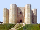
Castel del Monte (File 156-510) |
|
Portal Wing Design |
Introduction
Castel del Monte is oriented east, a common orientation in ancient architecture. An elaborate portal was added to the side of the plant octagon facing east, to create a front for the castle. The incorporation of a portcullis in the portal required a number of adjustments at the façade wall, in the portal wing. These changes included a small bump of the cross vault and the attached courtyard wall section toward the center of the plant. As a result, the perfect octagonal perimeter of the courtyard became distorted.
There are other minor distortions in the portal wing. Most likely, these are not chance variations to the design during construction, but some small and well-intended adjustments, probably related to efforts to correct the orientation of the portal.
Portal Wing
The task following the two initial phases of the plan development, the concept design and the tower modification, was most certainly to define a front for the castle. The octagonal ground plan solves the structural requirements but does not include features that suggest a location for a castle front. The plant has eight wings all similar and equal structurally, indistinguishable from one another. Accordingly, any of the plant octagon sides can serve as a front, by adding a portal, Fig. 1.
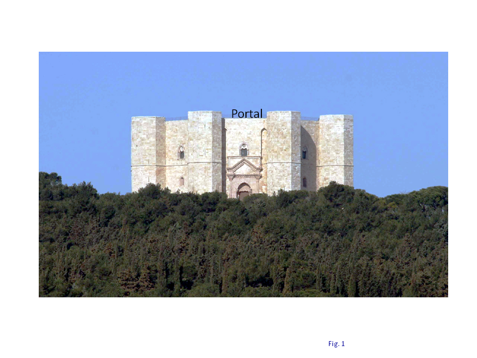
Fig. 1. Castel del Monte portal.
The introduction of a front required a modification to the plant design, involving only one wing of the plant. In contrast, the modification at the towers, addressed in the second phase of the design (the Plant Modified Design), was a systemic modification, affecting each tower and the whole plant, preserving the eight-fold rotational symmetry of the ground plan.
Scholars point out that the portal of Castel del Monte faces East, in the direction of Andria, a city beloved by Frederick II Hohenstaufen that built the castle. This is accomplished simply by setting the orientation of one of the major diagonals of the plant octagon 22.5° off the East direction. One of the plant octagon sides face east as a result and becomes the front for the castle, Fig. 2. A front was added to this side, resulting in a modification in this wing of the castle, Fig. 3.
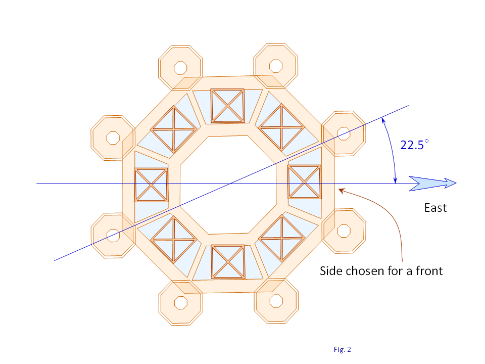
Fig. 2. Ground plant orientation for setting a front to the castle.

Fig. 3. Front added on the eastern side of the octagonal plant.
The façade wall is thick enough, 2.56 m, to accommodate the needs for an ordinary gateway. This would have left the chosen octagon side unmodified except for the doorway, in harmony with the plain and simple style of the façade wall. A portal was added instead on the outdoor side of the façade wall, Fig. 4. Presumably this was a design detail by Cistercians that most likely finalized the design and executed the construction.
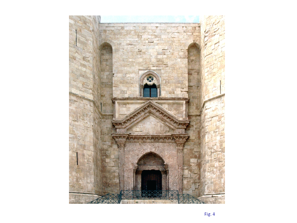
Fig. 4. Portal added to the front of the façade wall.
The designers envisioned adding a portcullis in front of the door. The portcullis is formed by a grating that slides up and down in vertical groves cut in the stone doorway, Fig. 5. The grating is missing nowadays at Castel del Monte; all that is left are the grooves in the portal stonework, Fig. 6.
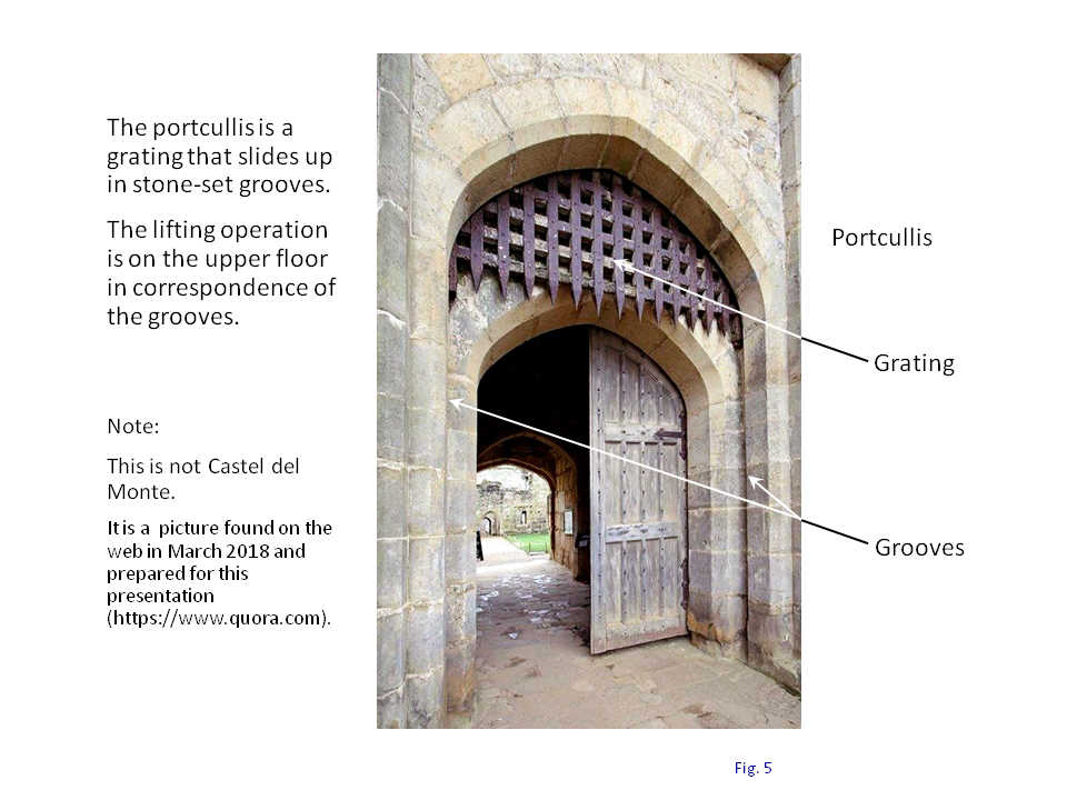
Fig. 5. Example of a portcullis.
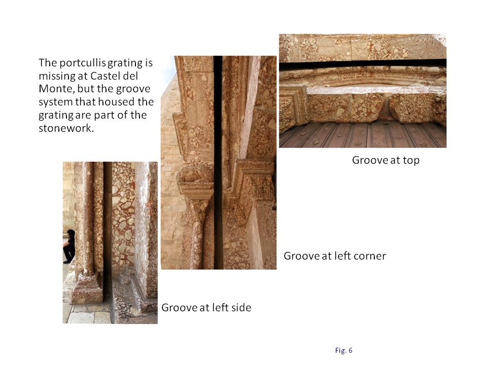
Fig. 6. Portcullis groove at Castel del Monte.
The addition of a portcullis requires an open space on the upper floor, accessible from the inside in correspondence of the portcullis grooves, for lifting the gate, Fig. 7. This required a reconfiguration of the façade wall on the upper floor, because the portcullis is located on the outdoor side of the façade wall.
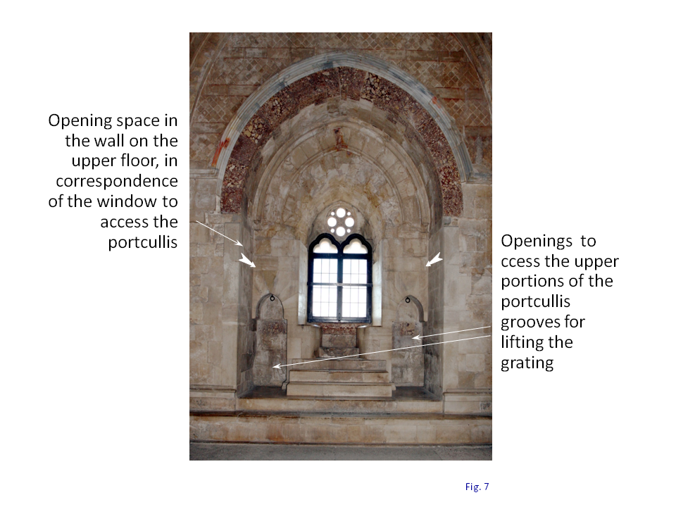
Fig. 7. Space on upper floor wall above portal, “Throne Room”.
The façade wall redesign includes two structural modifications: an inward widening of the façade wall on the ground floor, and an outward extension of the wall on the upper floor overhanging the doorway on the lower floor. Of course, this is a unique modification done only on one side of the octagonal façade wall, the one chosen as the front.
The cross vault has a square base with a dimension w on the ground floor, established in the concept design phase and preserved in the following plant modified design phase. It is a fixed dimension that could not be changed; all rooms on the ground floor have the exact same cross vault measure.
The widening of the façade wall on the ground floor is primarily inward, toward the center of the plant. This protrusion of the façade wall enlargement into the room space requires that the cross vault square and the attached portion of the courtyard wall in this wing of the plant octagon be moved inward toward the center of the plant, Fig. 8.
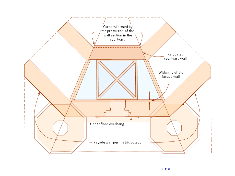
Fig. 8. Displacement of the cross vault and courtyard wall.
The plain repositioning of the courtyard wall in this wing of the plant octagon would create corners in the courtyard perimeter, Fig. 8. These corners are filled in with masonry, which returns the perimeter of the courtyard to the form of an smooth octagon. However, it is an irregular octagon, because of the distortions created by these modifications.
The irregularity in the courtyard octagon is one of the few anomalies in the otherwise perfect geometric forms of Castel del Monte. The irregular courtyard is a detail addressed by H. Götze, W. Schirmer, and other scholars. Before delving further into this plant detail, it is helpful to examine first the portal wall structure.
Portal Wall
The portal section appears in Fig. 4 like a medieval standard hanging down from the towers in front of the façade wall. A copy of the portal picture is shown in Fig. 9 with detailed annotations that highlight the various sections.
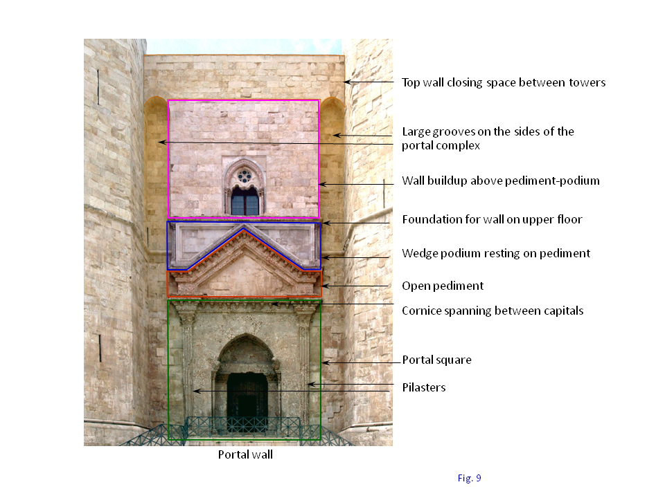
Fig. 9. Portal wall components.
Other details of the portal wall are revealed in the cross profile shown in Fig. 10, a reproduction of Schirmer’s work. Together with Fig. 9, they provide information along and across the portal wall.
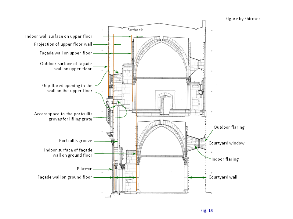
Fig. 10. Schematic of the portal wall.
The front of the castle is a sophisticated two-story design that merges the gateway on the ground floor with the overhanging upper floor. The ground floor doorway lines up with the façade wall and is framed between two pilasters, forming a square section, Fig. 9. The pilasters are topped by capital sections that suggest a support function for the structure above. Indeed, the pediment above and the matching wedge-podium further up provide a corbel-like structural function for the upper floor, Fig. 11. The overhanging structure extends 70 to 75 cm out from the façade wall octagonal perimeter, a measure noted on the roof, Fig. 12.
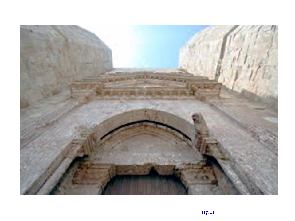
Fig. 11. Overhanging upper floor.
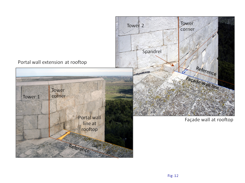
Fig. 12. Portal wall extension at rooftop.
The portal square, the pediment above, the wedge-podium on top and the upper floor wall form a stack of wall sections of the same width, Fig. 9. The rise of this stack accompanied by a gradual overhanging extension leave groove-like openings on both sides, between this center structure and the towers. The grooves are topped by arches near the roof where a plain wall spans between the towers.
The design uses these structural features together with decorative elements to create a transition from ground to roof that conceals the upper floor overhang and gives a sense of flatness, which is the feature for the other seven sides of the façade wall.
There are then two boundary lines defining the portal front: one is at the ground level where the doorway rises from the floor, Fig. 13; the other is at the roof where the extension of the upper floor is clearly delineated, Fig. 14. The reference in the analysis is the side of the regular octagon that delineates the outdoor perimeter of the façade wall, Fig. 8.
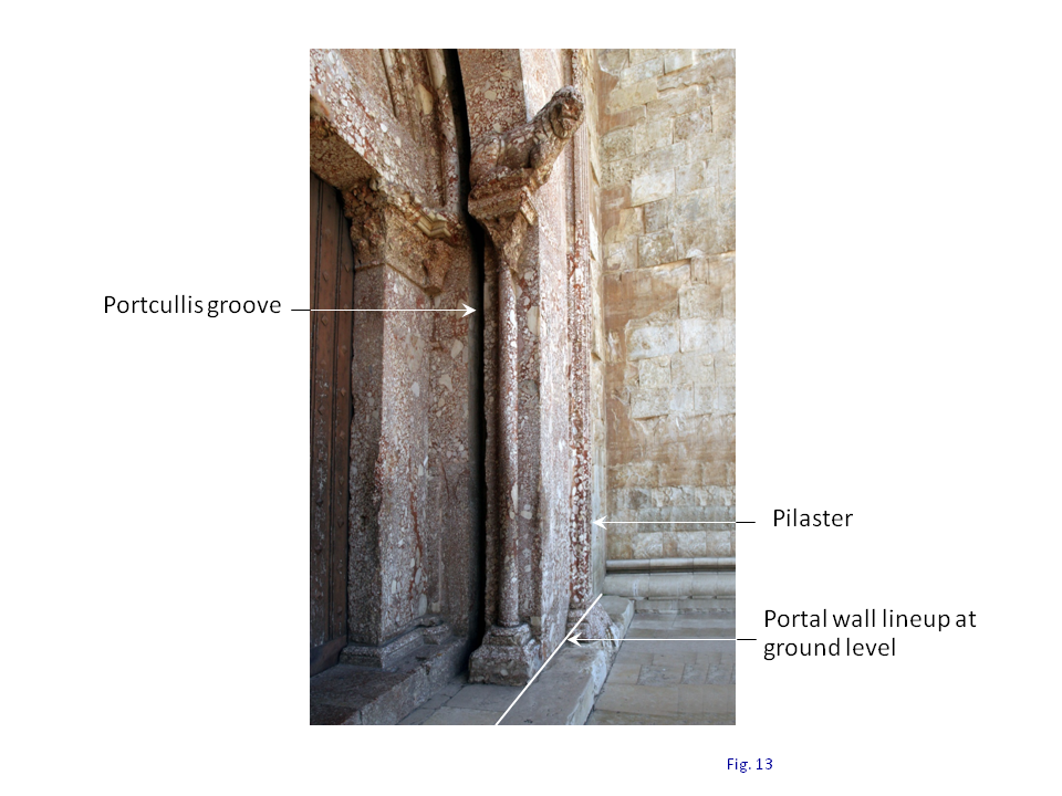
Fig. 13. Façade wall lineup on ground floor.
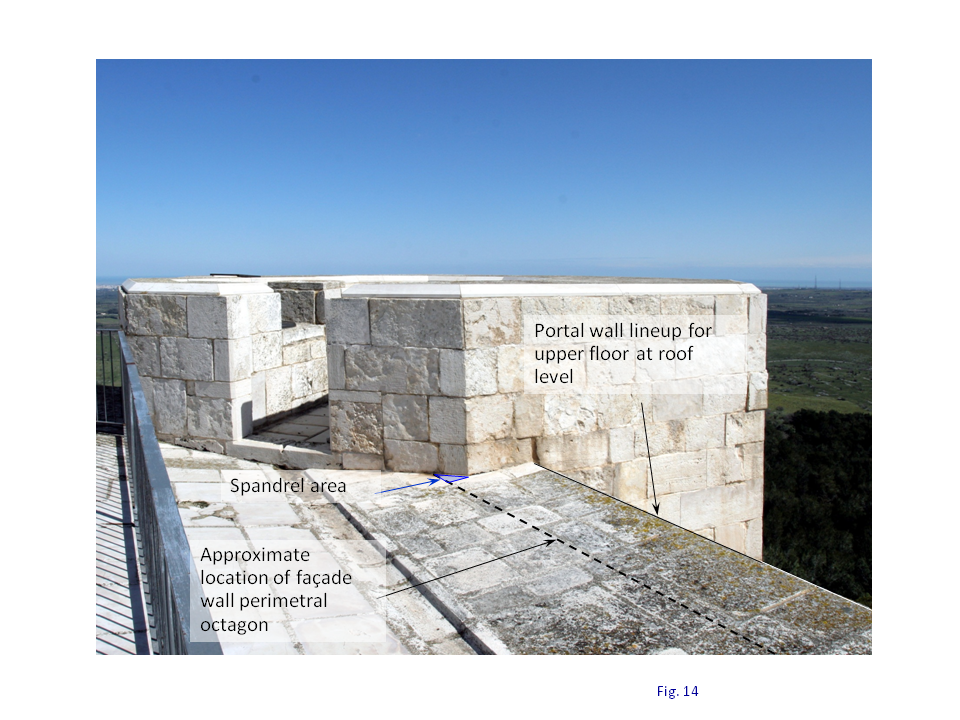
Fig. 14. Façade wall lineup on the roof.
The doorway on the ground floor seems to line up with this side of the façade wall octagon. Schirmer puts the radial distance of the doorway side from the center of the plant at a measure that is the same as the other sides of the façade wall, 20.26 m, ±1.5 cm, Fig. 15. However, there are some questions on this point.
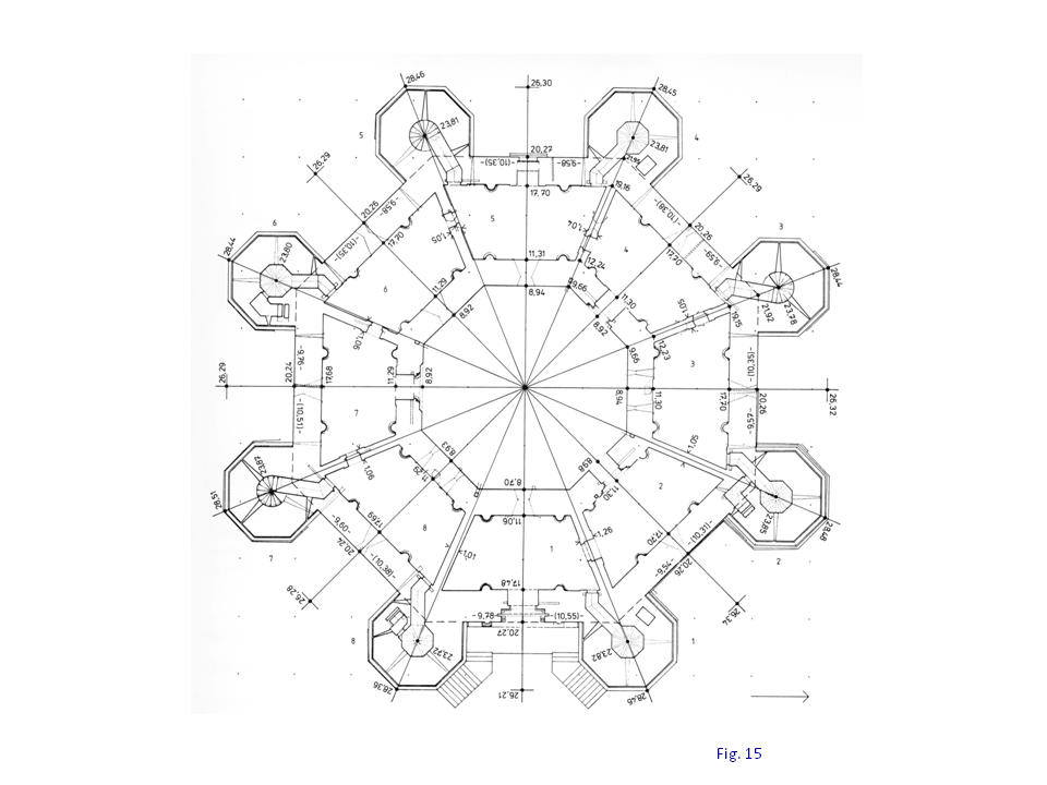
Fig. 15. Ground floor radial measures ? Schirmer.
The measure for the upper floor overhang is not addressed directly by Schirmer or Götze. It is estimated to be about 70 to 75 cm as indicated above, Fig. 12. It is theorized that the designers may have chosen an exact measure of two Castel-del-Monte-foot (“CdM-ft”) out from the tower corners, which are separated from the façade wall by the spandrel, Fig. 16. The resulting extension of the upper floor would then be 76 cm from the façade wall outer perimeter (2 x CdM-ft + spandrel = 2 x 30.2 + 15.4 =75.8).

Fig. 16. Detail of the upper floor extension measure.
Both Schirmer and Götze indicate that the width of the façade wall on the ground floor is 2.79 m. The width of the façade wall for the other seven sides of the façade wall is given by Schirmer as 2.56 m, ±1.5 cm, Fig. 15. Accordingly, the façade wall on the portal side is 0.23 m wider than the façade wall at the other seven sides on the ground floor.
There are some unresolved questions in the portal wing with regards to the precise location of the portal on the ground floor relative to the façade octagon perimeter, Fig. 17. Schirmer indicates that the façade octagon perimeter on the ground floor in the portal wing is at 20.27 m from the center of the plant, Fig. 15.
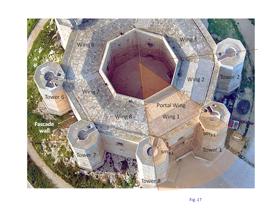
Fig. 17. Portal wing and façade wall.
The tower sides adjoining the portal (sm) are respectively 3.25 m for tower 8 and 3.30 m for tower 1, Fig. 18. The tower sides (sm) that intersect the façade wall, 16 of them on the ground floor, are all equal and have the dimension of 3.38 m at the end of the modified plant design phase in the study model. Götze indicates that this is indeed the nominal measure of these sides (sm), being the measure of the tower octagon side (s) plus the measure of the spandrel (m), (3.23 + 0.15 = 3.38). The tower sides (sm) are shorter in the portal wing, by 13 cm on the side of tower 8, and 8 cm on the side of tower 1, Fig. 18. These differences suggest that the portal front might be slightly in front of the perimetric octagon of the façade wall on the ground floor.
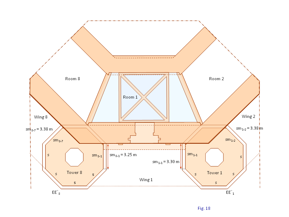
Fig. 18. Portal wall lineup at ground level.
To further complicate this matter in the portal wing, there is the difference between the side on tower 8 (sm8-1 = 3.25 m) and the side on tower 1 (sm1-1 = 3.30 m), Fig. 18. This difference is likely associated with another irregular measure reported by Schirmer. The distance of the tower footing outer corner in Fig. 15, also annotated as corner EE” in Fig. 18, from the center of the plant is a uniform measure of 26.30 m, ±3.0 cm, for towers 1 through 7, but is 26.21 m for tower 8, Fig. 15. It seems therefore that tower 8 is closer to the center of the plant than the other towers, by 9 cm on average. This likely explains the shorter measure for the side at tower 8 (sm8-1) compared to the side at tower 1 (sm1-1), although it cannot be excluded that the front follows an irregular lineup.
The data is not sufficient to resolve these questions. Nevertheless, the measures of the tower sides in the portal wing (sm8-8 and sm1-8) are both shorter than would be expected if the portal front on the ground floor were lined up with the side of the octagon that is the outer perimeter of the façade wall.
This matter does not hamper substantively the explanation for the relocation of the courtyard wall in the portal wing.
Courtyard Octagon
The widening of the façade wall in the portal wing causes a bumping of the cross vault room toward the center of the plant by 23 cm, Fig. 19. The courtyard wall section in the portal wing is similarly relocated closer to the center of the plant, but by a slightly larger amount.
The width of the cross vault room in the portal wing is 6.42 m. The width of the other seven cross vault rooms on the ground floor is 6.40 m, ±1.0 cm, Fig. 20. Accordingly, the room in the portal wing is wider than the others seven rooms by 2 cm; a small amount, just above the variance range of ±1.0 cm.
The width of the courtyard wall is uniform, an average of 2.36 m, ±3.0 cm, for all eight sides, Fig. 20. The width of the courtyard wall in the portal wing is 2.36 m, the same as the average around the courtyard wall octagon.
The courtyard wall section in the portal wing is then bumped by 25 cm, which is 23 cm due to the widening of the façade wall and 2 cm due to the larger cross vault room (23 + 2 = 25).
As mentioned earlier, the resulting corners that the relocated section would form in the courtyard with respect to the adjacent courtyard wall sections, Fig. 15, are filled in with masonry to provide a seeming regular octagon, as shown in Fig. 18 and 19. It is however an irregular octagon, because the resulting courtyard octagon side, d2-1-mod in Fig. 19, is longer than the side of the perfect courtyard octagon, d2-1 before the wall section relocation.
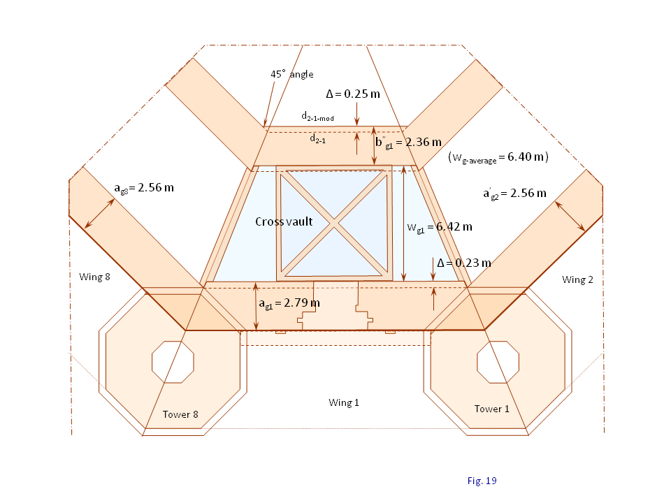
Fig. 19. Courtyard wall relocation.
The side of the regular courtyard octagon, d2-1 , measures 7.40 m at the end of the second phase in the design. Schirmer indicates the measures for the courtyard octagon sides in Fig. 20. These measures are shown again in Fig. 21, where it is also shown that the average measure of the courtyard octagon side for the five courtyard octagon sides that are not affected by the courtyard wall relocation in the portal wing is 7.40 m, ±3.5 cm.
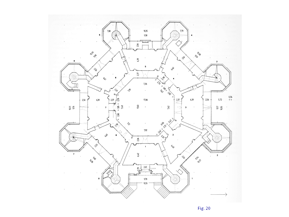
Fig. 20. Ground floor width measures ? Schirmer.
The courtyard perimeter is a perfect octagon per design and nearly so as implemented by the builders 800-years ago, except of course for the relocated side. The distance of seven courtyard sides from the center of the plant, excluding again the modified one, is 8.94 m, ±3.0 cm, according to Schirmer’s data in Fig. 15. Calculated trigonometrically from this datum, the nominal side of the courtyard octagonal perimeter should be 7.40 m (d2 = 2 x 8.94 x tan 22.5° = 7.40), which is the average measurement for the five unaltered sides in Fig. 21. The variance in these five measures is ±3.5 cm, 0.5% of the 7.40-m measure, a fairly high level of precision by medieval builders.
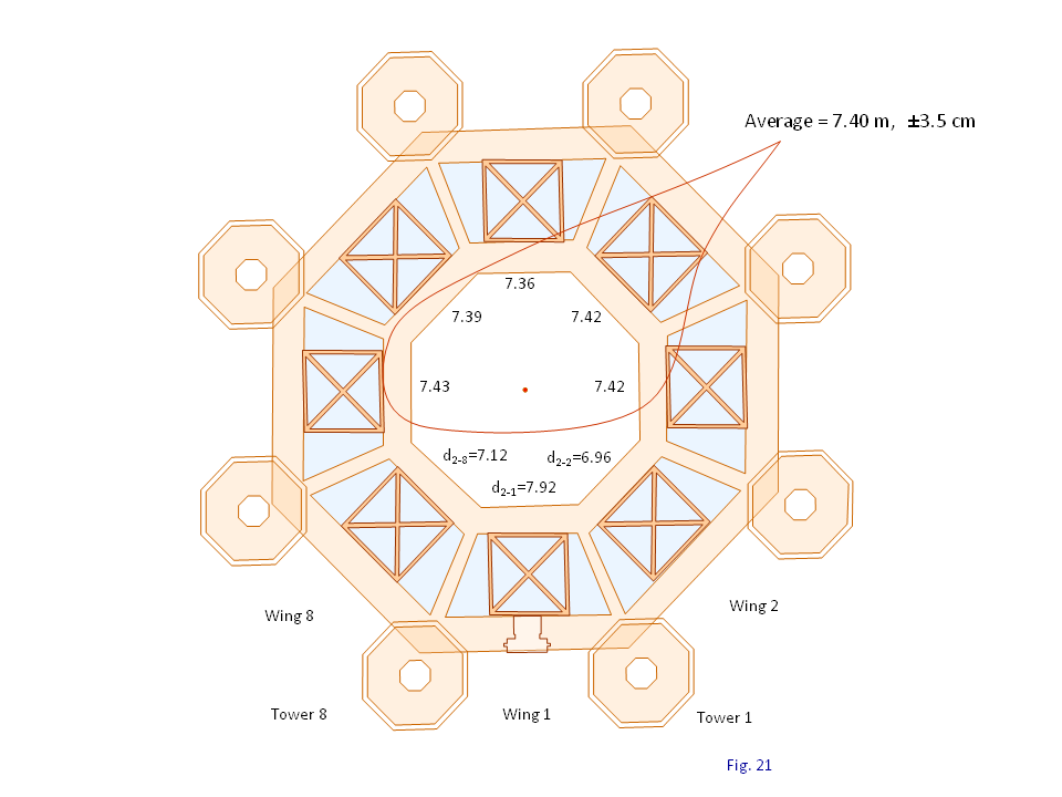
Fig. 21. Courtyard octagon side measures.
A geometric analysis is outlined in Fig. 22 for a relocation by 25 cm of the courtyard wall section in the portal wing. The corners that this protrusion creates in the courtyard, Fig. 15, are eliminated by extending the courtyard face line of the relocated wall until it intersects the wall on each side. The result is a lengthening of the courtyard side for the relocated wall section (wing 1) and a shortening of the courtyard face on both sides (wing 7 and wing 2).
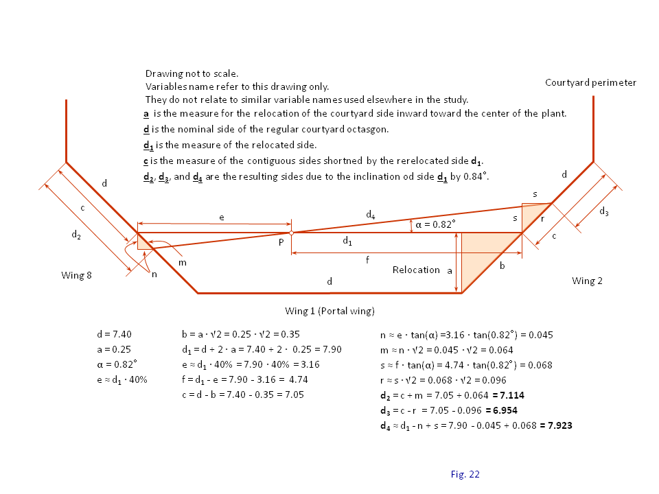
Fig. 22. Geometric analysis of the courtyard wall measures.
The resulting courtyard sides adjacent to the relocated wall section, one on each side, are shorter but equal (the measure c in Fig. 22). The lengthening of the relocated wall section and the shortening of the adjacent wall sides are related by the equilateral right-angle triangle formed by the relocation measure (25 cm) at the filled-in corners, triangle with sides a and b in Fig. 22. (The variable reference names in Fig. 22 apply to this figure only and are not related to similar reference names used throughout the rest of this study.)
The actual measures reported by Schirmer, shown in Fig. 20 and 21, show instead that the courtyard sides adjacent to the relocated wall section have different measures. Having shown that the nominal courtyard is a perfect octagon, the different measures are explainable only by a tilting of the relocated wall face line in the courtyard. This is a conclusion also reached by both Götze and Schirmer.
The inclination, angle a in Fig. 22, is estimated from the measurements provided by Schirmer (Fig. 20 and 21). The pivoting point for the inclination (P) is positioned on the relocated side, about 40% of the length of the relocated side from wing 8, as shown in Fig. 22.
The analysis in Fig. 17 shows that indeed the three nonstandard sides calculated geometrically, d2, d3, and d4 in Fig. 17, match exactly the measures reported by Schirmer, Fig. 21. The modifications for this exact match are them:
• courtyard side by 25 cm (side d1, Fig. 17) • A pivoting point (P, Fig. 17) located on the parallel-relocated octagon side, at four-tenth the length of the relocated side from wing 8 • An inclination angle (a, Fig. 17) of 0.82°counterclockwise
Irregularities in the Portal Wing
The widening of the facade wall in the portal wing is by 23 cm, which is 76% of a CdM-ft (30.2 cm). Why would the medieval designers have chosen such an odd measure for widening the façade wall? It does not seem to have a geometric or other proportional relationship to anything else in the plant.
Notably, the medieval designers used values that are even multiples of a foot (CdM-ft) in those few instances where geometric proportionalities were not forthcoming. A major example is the room dividing wall on the ground floor for which the designers could not find a geometric construct from which to derive a measure, and thus chose a subjective measure of three feet exactly. Together with the finishing layers (one on each side), the width of the wall is 1.05 m (3 x 0.302 + 2 x 0.075 = 1.056).
Schirmer’s measurements, Fig. 15, indicate that indeed the width of the dividing walls is 1.044 m, ±2.5 cm, for seven of the dividing walls on the ground floor. Another example is the upper-floor wall extension in the portal wing that was discussed above to likely be two feet exactly.
A measure of 23 cm, essentially three-quarter of a CdM-ft, seems an odd choice that cannot be explained. This measure is 7.2 cm short of the CdM-ft (30.2 cm). Given that there is an unresolved question of 5-8 cm related to this wall, as discussed above, this gives rise to a thought that indeed the designers may have chosen a measure of an even foot for the façade wall widening on the ground floor; but this needs to be reconciled with more detailed information and data at the portal.
The relocation of the cross vault contravenes the design rule in the concept and then in the modified design at the towers, which is that all cross vaults need to be located at the intersections of the plant octagon minor diagonals for proper lining of the cross vault lateral thrusts with the towers. A relocation of 23 cm for the cross vault in the wing direction comports a relocation of 16 cm of the cross vault diagonals away from the established plant minor diagonals.
This is a minor deviation considering the large and heavy masonry already defined, and the fact that this is a small measure in relation to the footing dimension of 38 cm, which is a measure that medieval designer used in dealing with structures involved with lateral thrusts.
Furthermore, this design change was made later in the development process, probably by people that had somewhat different design priorities and concerns, and a lesser focus and preoccupation with cross vaults. As noted elsewhere in this study, the stonework for the designed cross vaults, like the groin arches, tas-de-charges, support columns, etc., may have been farmed out as separate jobs for “just-in-time” delivery, and could not be readily changed.
Finally, it is noted that the resulting courtyard octagon is an irregular geometric form, although it seems to have originated from a normal octagon. While the inward parallel relocation of the octagon side by 25 cm (side d2 in Fig. 22) seems a coherent geometric operation, the tilting of this side by 0.82° (side d4 in Fig. 22) seems like an arbitrary move, with no obvious explanation.
Furthermore, such a tilting has implications for the courtyard wall section and the cross vault in the portal wing. If the trapezoidal room with the square cross vault at its center is positioned in a regular geometric manner, with sides parallel to the plant octagons, as with all the other seven cross vaults on the ground floor, the width of the courtyard wall in the portal wing would have a variable width, because of the inclination of its exterior lining in the courtyard, which is tilted.
Schirmer reports a width of 2.37 m for this wall, presumably at its midpoint. This would be consistent with a situation where the width of this wall was slightly larger on the side of wing 2, near the nominal width at its center, and slightly smaller on the side of wing 7.
On the other hand, if this courtyard wall section is perfectly uniform along its length, then the implication is that the cross vault square base and the trapezoid room built around it are similarly tilted by 0.82°. It could also be that the trapezoidal shape of the room is slightly distorted, to make up for uniform walls at both the façade and the courtyard sides, leaving the cross vault still a perfect square. It has been noted already that the room width is slightly irregular, about 2 cm wider than the others on the ground floor.
The portal wing seems to have a number of minor irregularities. Most of them are small, unnoticeable to the naked eye, and often only slightly above the normal range of other structures around the castle.
There are definitely some changes with the addition of a portal at the facade wall, but there are some unresolved questions concerning the correct location of the portal wall at the ground floor, at this point in the examination, Fig. 23. The positioning of the portal wall per the data provided by Shirmer needs to be reconciled with measurements of the tower sides in the portal wing.
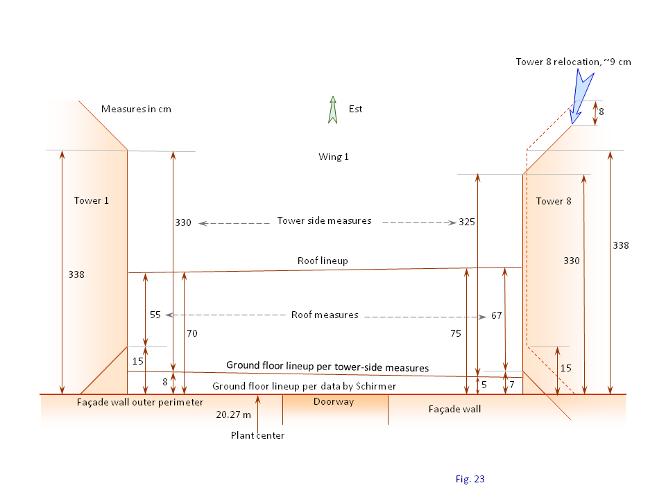
Fig. 23. Measurement notes for the portal front.
Part of the issue is knowing what to measure in relation to the question being addressed. Another issue is that many of these deviations are small, sometimes near the limit of precision achievable and other times barely above the variation range of similar structures around the castle, which itself is very small. Certainly, there would be some deviations as medieval builders endeavored to realize the construction following the design specifications, and more distortions as the castle has undergone numerous restorations over a century. The restorations started with the acquisition of the castle by the State in the middle of the 19th century, and have been substantive, Fig. 24.
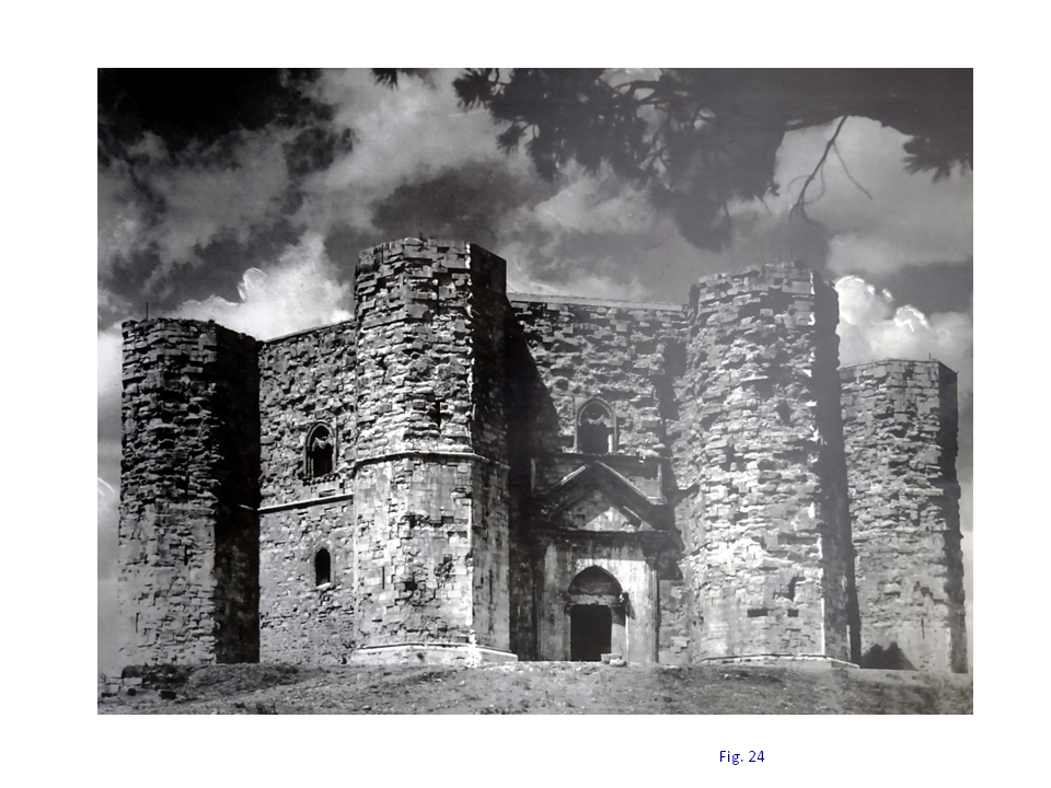
Fig. 24. Castel del Monte circa 1900.
It is remarkable, however, that these distortions are nevertheless still small. For example, the distance of the footing outer corner from the center of the plant is 26.30 m, ±3 cm, for seven towers (Fig. 15), a precision of 0.1% by the medieval builders. The spandrels, which are likely the elements most affected by restoration, measure 15.4 cm, ±2.5 cm, for 11 identifiable spandrels on the roof.
The noted irregularities are not unintended construction errors. They are likely intentional modifications, possibly compounding decisions at separate times in the construction, which is difficult to decipher, especially when the precise geometry remains unresolved. It is possible that the repositioning of tower 8 closer to the center of the plant by 9 cm at a first time, the relocation of the cross vault and the attached courtyard wall section at a second time, and the associated modifications could be related to the orientation of the portal and the “throne” room on the upper floor, which is a subject of interest by some scholars.
Conclusions
The addition of a portal to give a front to the castle resulted in a number of design changes throughout the wing, from the façade to the courtyard walls. The room width in the portal wing was preserved, but the room was bumped toward the center of the octagon to make room to a wider façade wall. The addition of a portal required widening the façade wall on the ground floor to accommodate a portcullis, and an overhang on the upper floor to open up space needed in correspondence of the portcullis to operate the gate lifting.
Various structural features together with artistic decoration give the front the sense of flatness as in the other seven sides for the castle. The courtyard wall section in the portal wing also retains the initial design width and is bumped jointly with the room, resulting in a distorted octagon for the courtyard perimeter. There are other small distortions throughout the portal wing; the study is challenged by measurement data as made available in the literature
© Lanera.com