Neutral-to-Earth Voltage |
|
|
|
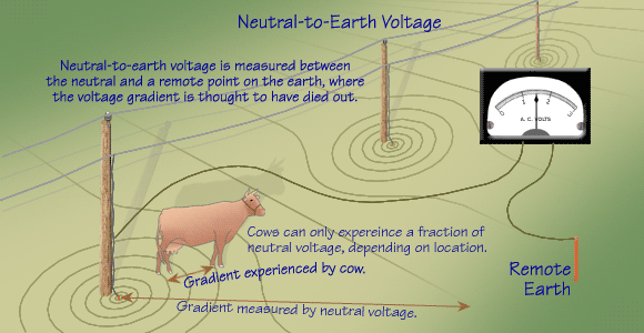
The voltage measured between the neutral conductor (or a ground lead connected to the neutral
conductor) and a remote point on the earth is the highest gradient voltage possible in most
cases. Neutral-to-earth voltage may be measured either on the supply circuit
(also known as the utility or primary neutral-to-earth voltage)
or on the utilization circuit (also known as the customer or secondary neutral-to-earth voltage).
|
|
The neutral-to-earth voltage is a special voltage gradient measurement in the earth.
In our analogy to a flight of stairs, a voltage gradient is the voltage measured between
any two steps chosen arbitrarily.
The neutral-to-earth voltage is equivalent to the difference in height between the top
and the bottom steps.
It characterizes the maximum possible gradient situation, much as total elevation
characterizes the height of a mountain.
|
|
Neutral-to-earth voltage measurements are made for
diagnostic purposes only. Knowing what happens to neutral-to-earth voltage under varying system conditions
can be extremely useful in a determination of stray voltage sources and appropriate
mitigation alternatives.
|

|
 
|
|
Neutral-to-earth voltage is not stray voltage. This is an important difference.
Stray voltage is a voltage gradient measured between two points
that a cow may contact at the same time (two nearby steps in a stairway).
Neutral-to-earth voltage, on the other hand, is a gradient measured over a distance too great
for a cow to reach.
Neutral-to-earth voltage is the maximum gradient. Measuring neutral-to-earth voltage typically
involves locating a reference point on the earth far from the area of concern and outside
of the electrical system's influence. Usually a cow cannot contact the
neutral conductor, or some object connected to the neutral, and a remote point on the earth
at the same time and is therefore not exposed to neutral-to-earth voltage.
|
|
The neutral-to-earth voltage changes slightly
from location to location on the neutral system.
The resistance of the wires and connectors allows for these slight and
regular changes in voltage along the neutral conductor. |
|
Locating the reference ground rod can be a difficult task. If not done properly,
considerable variability and errors in measurement may result.
The reference point must represent the earth far away, yet
be close enough to make measurement possible.
The reference rod location should be far
from the area of concern and from any other electrical system or electrically
conductive object in the area. A good way to check the location selection
is to make multiple neutral voltage measurements
using different remote earth reference points. If the measurements
differ significantly, there may be a problem with the choice of reference points. |
 
|
|
Some portion of the neutral-to-earth voltage appears on all metallic structures that normally are
bonded to the farmstead neutral system (i.e., waterlines, stanchion pipes, etc.).
Many of these structures are the grounding electrodes that allow
current to flow from the neutral to the earth or vice versa.
The currents flowing on these electrodes can come from many sources, as we have learned.
It follows that the neutral-to-earth voltage itself can be broken down into various components
according to the current source.
|
|
In conclusion, neutral-to-earth voltage is an important diagnostic measurement that provides valuable
clues about stray voltage levels and sources. It is not, however, measured in the same
way and should not be confused with stray voltage.
|
|
|


|
